Shanghai Daiyu Education Equipment Manufacturing Co., Ltd.
Language:


| serial number | Configuration name | Model specifications | unit | quantity | Remark |
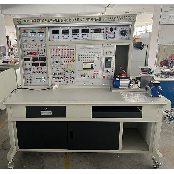
| 1 | Experimental screen | tower | 1 | ||
| 2 | Experiment table | tower | 1 | ||
| 3 | Electrician/electronic experiment hanging box | Basic circuit tr*ning (1) | set | 1 | |
| Basic circuit tr*ning (2) | |||||
| AC circuit tr*ning (1) | |||||
| Basic circuit tr*ning (3) | |||||
| Comprehensive skills tr*ning for electricians (1) | |||||
| Comprehensive skills tr*ning for electricians (2) | |||||
| Electronic technology tr*ning (1) | |||||
| Electronic technology tr*ning (2) | |||||
| Relay contact control (1) | |||||
| Relay contact control (2) | |||||
| Relay contact control (3) | |||||
| 4 | PLC hanging box | PLC Mitsubishi FX1N-40mR host hanging box | set | 1 | |
| 5 | PLC tr*ning hanging box |
PLC tr*ning module one: 1. Music fount*n simulation control 2. Clicker simulation control 3. Assembly line simulation control 4. Crossroad traffic light simulation control 5. Automatic rolling mill simulation control 6. Sky Tower Light/TV Tower Radio Wave Simulation control PLC tr*ning module two: 1. Automatic feeding and loading/conveyor belt simulation control 2. Multiple liquid mixing devices/mixers simulation control 3. Vending machine simulation control 4. Water tower automatic water supply simulation control 5. M*l sorting simulation control PLC tr*ning module three: 1. Basic input/output experiment 2. Four-story elevator automatic control 3. Intermediate relay |
set | 1 | |
| 6 | Frequency conversion speed regulation hanging box | Mitsubishi FR-720 hanging box | set | 1 | |
| 7 | Motor guide r*l and optical code disk speed measurement system | set | 1 | ||
| 8 | Three-phase squirrel cage asynchronous motor | 380V Y/△ | tower | 1 | |
| 9 | stool | set | 2 | ||
| 10 | Guiding book | set | 1 |
|
 Wechat scan code follow us

24-hour hotline+86 18916464525

Phone18916464525
ADD:Factory 414, District A, No. 6, Chongnan Road, Songjiang Science and Technology Park, Shanghai ICP: Sitemap