Shanghai Daiyu Education Equipment Manufacturing Co., Ltd.
Language:

PRODUCT

PRODUCT CENTER

DyyCCG-2 Industrial Sensor Experimental Platform

Release time:2024-04-28 07:00viewed:times
  • DyyCCG-2 Industrial Sensor Experimental Platform
1. Equipment introduction:
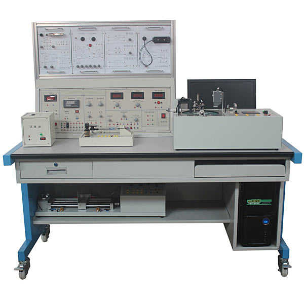
This tr*ning platform breaks the original independent tr*ning model of multiple courses, integrating circuit analysis, analog electronics, digital electronics, microprocessors, sensors , FPGA technology, virtual instrument technology, embedded technology, etc. Multiple courses are organically combined under a comprehensive practical tr*ning system, and integrated into application software such as Labview, Protel, and C language to provide students with a practical tr*ning platform that combines understanding, system integration, innovation and scientific research, and cultivate students' mastery of The latest electronic design concepts, tracking cutting-edge technology trends in the electronic field, to meet the needs of cultivating modern innovative talents.
This platform can not only meet the theoretical and practical tr*ning requirements of a single course, but also serve as a tr*ning platform for the cultivation of comprehensive innovation capabilities in vocational colleges. It can also be used as equipment for curriculum design, graduation projects, and competition tr*ning.

2. Product features:
1) Suitable for comprehensive tr*ning of professional abilities in electronic information, computers, automation, communications and other majors.
It breaks through the original tr*ning model and organically integrates the experimental content of multiple courses. Integrate knowledge points from various courses such as electronic technology, circuit principles, microcontrollers , sensors, virtual instruments, FPGA, embedded and other courses for comprehensive vocational skills tr*ning.
3) The practical tr*ning environment can well solve the hardware environment problems of course design, graduation project and pre-competition tr*ning.
4) The three stages of practical tr*ning for students cultivate students' hands-on design operations, system integration, teamwork and other abilities and Habit.
The first stage is for the experimenter to select appropriate functional circuits based on specific experimental requirements, form a target system based on the technical parameters of each functional circuit, then conduct functional and parameter tests on the target system, and finally complete the experimental test report.
In the second stage, the experimenter independently designs and produces a cert*n functional circuit in the system. From principle design, component selection, circuit board drawing, production, installation and debugging. Realize the replacement of the original functional circuit.
Through the first stage of experimental tr*ning, students can be helped to establish a systematic concept. Through the second stage of tr*ning, students can be given a complete process of research and development. These two stages of experiments can achieve the best experimental results in the shortest time. At the same time, the functional circuits developed by students can be used as experimental modules for the next generation of students. After several years of accumulation, a rich functional circuit library can be accumulated for the laboratory
. The third stage of tr*ning involves multiple experimenters working together to complete the design, production and debugging of a system. First, all participants jointly completed the overall scheme design of the system, and then divided the functions, which were completed by each experimental student. The completion process was the same as the second phase of tr*ning. At this stage, students are m*nly tr*ned to work as a team and help each other, experience the fun of solving problems together, and share experiences and lessons.
5) Modular hardware structure and practical tr*ning teaching mode that integrates theory and practice.
This tr*ning teaching platform consists of a control platform, standard modules and actual objects. The tr*ning of various knowledge points is reflected through standard modules. Comprehensive tr*ning is completed using actual objects and one or more standard modules. Through practical tr*ning, students can know the application of single knowledge points and the relationship between systems, so that the learned content can be connected in series with each other.
6) Effectively cultivate students' system integration capabilities
and provide students with experimental modules with various functions. Students can select appropriate experimental modules according to the needs of the project, connect and combine them to form an experimental system, and then match it with appropriate software or control methods, that is, Can complete an experimental project. Cultivate students' system integration abilities. Provide students with a practical tr*ning platform that is similar to their future work process and environment, so that students can quickly adapt to work after graduation.
7) Better save funds for the construction of tr*ning rooms for the school.
On the basis of meeting the design and comprehensive experimental projects, this experimental device can still carry out the original experimental contents such as analog electronic technology, digital electronic technology, and circuit analysis.
 
3. Technical conditions
1. Working power supply: single-phase three-wire AC220V±10%/3A/50Hz/power supply;
2. Overall machine capacity: less than 1kVA;
3. Size: length × width × height of the control panel: 1.3m × 0.4 m×0.5m;
length×width×height of the tr*ning table: 1.8m×0.8m×0.8m;
4. Weight: less than 200kg.
5. Virtual multimeter parameters:
AC voltage range points: 10, 50, 250, 1000
DC voltage range points: 0.25, 1
, 2.5, 10, 50, 250, 1000 ohm range points: x1, x10,,100 ,,1000,,1K,x10K,x100K
ammeter gears: 50μa, 0.5, 5, 50, 500
BATT: 1.2-3.6V, RL=12Ω
BUZZ: R×3
infrared emission detection function: vertical angle ±15° distance 1 -30cm
transistor measuring hole

4. Technical description
1. Equipment personal safety protection
It has a current leakage protection function and complies with the national low-voltage electrical safety standards.
2. Equipment safety protection functions
1) DC voltmeters, DC ammeters, AC digital millivolt meters and other measuring instruments all have over-range protection functions
2) Constant voltage sources, constant current sources, signal sources, DC regulated power supplies, etc. all have short circuit and open circuit protection function.
3. M*n control screen and tr*ning table
The m*n control screen is made of 1.2 mm cold-rolled steel plate with plastic spraying process, and the structure is simple and elegant. The top and rear adopt the form of door opening, which can be opened for easy rep*r and m*ntenance. The m*n control screen is designed with DC stabilized power supply, constant voltage source, constant current source, DC voltmeter, DC ammeter, signal source and frequency meter, AC digital millivolt meter, virtual acquisition card and computer control unit, mesh board and other instruments meter. The control panel is equipped with 4 single-phase three-pole power sockets for use by various instruments and meters.
The tr*ning table adopts an iron spray-cast structure, which is solid in structure and beautiful in appearance. Computer hosts, monitors and keyboards can be placed above and below the tr*ning table, and various tr*ning modules can also be stored.
4. Instrument description
1) DC digital voltmeter: measurement accuracy is 0.5, measurement range is 0-200V, measuring range is 200mV, 2V, 20V, 200V four-speed direct key switch, with over-range protection function, with computer interface .
2) DC digital ammeter: The measurement accuracy is 0.5 level, the measurement range is 0-2A, the measuring range is 2mA, 20mA, 200mA, 2A four-speed direct key switch, has over-range protection function, and has a computer interface.
3) Digital multimeter
: Equipped with a three-and-a-half-digit digital multimeter, which is fixed on the panel of the experimental screen. The experimental screen provides 9V power to the multimeter, eliminating the need to frequently replace the multimeter battery in the laboratory.
4) AC millivolt meter: Measuring frequency range 5Hz-1MHz, measuring voltage range 0-700V sine wave effective value voltage, divided into five ranges of 200mV, 2V, 20V, 200V, 700V, 3 and a half digit display, with computer interface.
5. Power supply technical description
1) Dual-channel 0-30V constant voltage source and digital monitoring instrument.
Adjustment range: 0-30/1A continuously adjustable; voltage stability <3%, ripple voltage <1mV, adjustment accuracy 1%;
with Three and a half digit display monitor, which can display 0~30V voltage output through switch switching, with computer interface; it has short circuit protection and automatic recovery functions.
2) 0-200mA constant current source and digital monitoring instrument
adjustment range: 0-200mA continuously adjustable, starting from 0.00mA; maximum open circuit voltage: 30V, with open circuit protection function, including three and a half digit display and monitoring, with computer interface.
3) DC fixed power supply
provides ±12V, ±5V/1A four-way DC regulated power supply. The power supply is equipped with over-current and short-circuit protection functions.
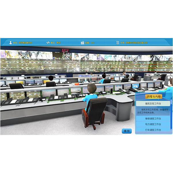
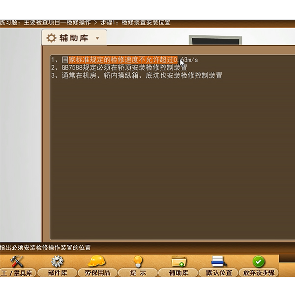
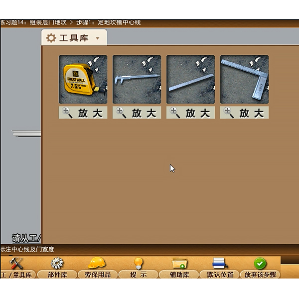
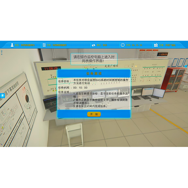
6. Virtual simulation system.
Microcontroller, PLC programmable design and control virtual simulation software.
This software is developed based on unity3d. It has built-in task books and experimental prompts. It adopts the form of three-dimensional roaming and can control movement through the keyboard, the mouse to control the lens direction, and the mouse wheel to control the screen. Far and near, it can rotate 360 ​​degrees, and there are electrical diagrams p*nted on the three-dimensional wall.
1. Equipment component assembly: Follow the highlighted prompts to find the component control rack. You can drag components from the component library according to the electrical component layout diagram and place them on the component control rack. The component library is equipped with control panels, switching power supplies, micro relays, and PLCs. , frequency converter, stepper motor , AC motor, servo motor, servo driver, stepper driver, interface board, operation panel, circuit breaker, servo motor interface, digital display voltmeter, there will be a prompt when the selection is wrong.
2. Technical indicator measurement: Select the multimeter to check the servo motor connection cable and the servo driver with BOP panel. Adjust the left and right buttons to the ohm level, drag the black and red test leads and insert them into the R, S, T, U, V, W and ground phases respectively for testing. For resistance value, according to the highlighted prompt, find the power switch in the scene, drag the pen or multimeter to measure whether the power is on.
3) Electrical component connection: According to the electrical wiring diagram, connect the power line and control line, highlight the interface, connect the driver, interface board, power line, servo motor, encoder, PLC, and relay in order, and turn on the m*n power supply After turning on the switch, servo power switch, and faulty circuit switch, a fault code will be prompted, and you can select the cause of the fault from three items.
4) Parameter adjustment test: Turn on the power to adjust the speed, set the driver parameters according to the requirements of the mission statement, perform inching control/analog speed adjustment/multi-stage speed control, and observe the three-dimensional servo motor motion control. Select any of the 6 PLC programs and then adjust the servo drive analog speed. The PLC parameters are adjustable. Set the drive parameters and enter the three-dimensional servo motor motion control interface and electrical display interface. The operation panel is equipped with servo start, low speed, medium Speed, high speed, servo stop, torque limit, abnormal reset, forward/reverse rotation selection, 0-10 sliding control (the electrical panel displays the value in real time).
5) Inspect the three-dimensional virtual simulation machine of the servo system mask machine, observe its structure, inject fault points, select multiple fault causes, and locate faults. Connect the fault causes with the corresponding detection and positioning methods, and troubleshoot after selecting the correct ones. Connect the cause of the f*lure with the corresponding solution.
6) Control process plan, optional single machine mode and online mode of inching control/analog speed regulation/multi-stage speed regulation control, call up the control panel, display the operation of 3 production lines, perform real-time control, optional inching, low and medium High speed, start and stop control, adjustable speed. According to the control plan, the system automatically determines the performance of the production line and submits a disclosure record.
M*ntenance of electricians, electronic motors and vocational qualification tr*ning assessment simulation software.
This software is in apk format and can be used on PC or mobile. This software can set faults manually or automatically. This software uses the green color in the circuit diagram. The box selects to manually set the fault point (up to 39 fault points can be set), or the system can automatically set a random fault point, a random two fault points, a random three fault points, and a random four fault points. , randomly set five fault points. This software has functions such as toolbox, component library, magnifying glass, circuit diagram, etc. You can select a multimeter for detection through the toolbox, select appropriate components through the component library, and clearly understand each element through the magnifying glass. Devices and circuits. This software allows students to understand the working principle and circuit structure of the motor star-delta start control circuit through the setting of faults in the motor star-delta start control circuit and various investigations.
Virtual spectrum analyzer, logic analyzer, oscilloscope, three-meter simulation software:
This software is in apk format and can be used on PC or mobile terminals. The functions of this software are: resistance measurement, AC voltage measurement (measuring transformer, if the multimeter burns out when measuring the transformer, black smoke will emit prompts and can reset the multimeter), determine the polarity of the transistor, measure the DC voltage (the light turns on when the ammeter is turned on), measure the DC current, and determine the quality of the capacitor. This software can drag the red and black pen tips at will. When the two pen tips are dragged and positioned on the object to be measured, a red circle will be displayed. If the positioning is not accurate, no red circle will be displayed, and when incorrect operations are performed (such as the wrong range selected, If the measured data is wrong, etc.), the meter pointer will not respond, prompting errors and re-measurement, etc. This multimeter can select AC voltage gear, DC voltage gear, resistance gear, current gear, resistance adjustment to 0, and can enlarge the display data. Clearly view the measured data size. Students can learn the correct use of multimeters through this software.
Mechanical tr*ning safety education virtual simulation software: This software is developed based on unity3d. The software adopts the form of three-dimensional roaming. Movement can be controlled by the keyboard and the lens direction can be controlled by the mouse. It is equipped with mechanical safety distance experiments, mechanical safety protection device experiments, and mechanical safety protection design. For the basic assessment, when the experiment is in progress, the three-dimensional roaming screen uses arrows and footprints to prompt the user to move to the experimental location. The circle around the mechanical object shows the working radius. The experimental process is accompanied by a dialog box reminder of the three-dimensional robot.
A. The content of the mechanical safety distance experiment includes the safety distance experiment to prevent upper and lower limbs from touching the danger zone (divided into two fence heights and opening sizes). After selecting to enter, GB23821-2009 "Mechanical Safety to Prevent Upper and Lower Limbs from Touching the Danger Zone" pops up in front of the camera. "Safe Distance" requirements, error demonstration: The experimental process is that after the human body enters the working radius of the mechanical object and is injured, the red screen and voice prompts that the human body has received mechanical damage, and returns to the original position and conducts the next experiment. The last step is the correct approach.
B. Mechanical safety protection device experiments are divided into safety interlock switches, safety light curt*ns, safety mats, safety laser scanners and other protection device experiments. Optional categories (safety input, safety control, safety output, others), manufacturers, products List (safety interlock switch, safety light curt*n, safety mat, safety laser scanner, safety controller, safety relay, safety guardr*l). There is a blue flashing frame reminder at the installation location. Experimental process: select the safety guardr*l and install it, select the safety interlock switch (or select the safety light curt*n, safety mat, safety laser scanner) and install it, select the safety controller and install it in the electrical control box , select the safety relay and install it in the electrical control box, click the start button on the electrical control box. If you enter a dangerous area, the system will sound an alarm and the mechanical object will stop working. Select the reset button on the electrical control box to stop.
C. The basic assessment of mechanical safety protection design requires the completion of the installation of the mechanical safety system, and the correct installation of safety guardr*ls, safety interlock switches, safety light curt*ns, safety mats, safety laser scanners, safety controllers, safety relays, 24V power supplies, signal lights and Emergency stop button, the assessment is divided into ten assessment points. Some assessment points have 3 options, which are freely chosen by the students. After selecting the final 10 assessment points, submit for confirmation, and the system will automatically obt*n the total score and the score of each assessment point. .
D. The software must be on the same platform as a whole and must not be displayed as separate resources.
E. At the same time, we provide customers with the VR installation package of this software to facilitate users to expand into VR experiments. VR equipment and software installation and debugging are not required.
5. Sensor secondary circuit design and application tr*ning unit
This experiment is equipped with basic water tanks, pipelines, electromagnetic pumps, etc., and uses different industrial liquid level measurement sensors to form a variety of liquid level detection systems. The sensors av*lable include: str*n Type liquid level gauge, etc.
Through experiments, you can familiarize yourself with installation and test methods, application characteristics, measurement ranges, and installation conditions, and master accuracy analysis methods.
Computer control means that students can program and debug by themselves. Enhance students' practical ability and practical tr*ning ability. Manual control is to directly act on the device, such as outputting a current or voltage. Instrument control means direct output and collection of instruments, and all data can be displayed on the computer.
This device has multiple safety protections and provides IEC standard signals and related test points for microcontroller access for programming experiments.
1. Technical indicators
1), power supply: AC220V±10%50HZ±5%1A with good grounding
2), overall dimensions:
Experiment control box size: not less than 500mm (length) × 300mm (width) × 500mm (height)
3 ), weight: about 15kg
2. Experiment content
Sensor experiment:
1) Experiment to understand the working principle of the turbine flow transmitter
2) Experiment to understand the calibration method and working principle of the liquid level transmitter
3) Experiment to understand the working principle of the liquid level switch
Control Experiments:
1) Liquid level PID control experiment
2) Liquid level configuration control experiment
3) Flow PID control experiment
4) Flow configuration control experiment
5) Switching quantity test experiment
3. Configuration plan:

name model quantity
Micro Turbine Flow Meter LWGY-10A 1
Pressure Transmitters PT311B-5K233 1
RS485/RS232 converter   1
Micro st*nless steel water tank   1
Micro plexiglass experimental water tank   1
The electromagnetic valve   1
Manual valve   1
Micro magnetic pump   1
controller 4 analog inputs 4 analog outputs 1
 
6. Temperature control experimental device
can quickly heat up and cool down quickly. Its important structural features are small, compact, beautiful and safe. The device consists of an experimental temperature box, a heater, a thyristor voltage regulating module, a fan, a K-type temperature sensor and a Pt100 sensing transmitter. It can be combined with the host computer to form a temperature detection and closed-loop temperature control system. Communicate with the host computer through AD data collection . Control parameters can be set in the host computer. The host computer software uses VC\C++, MCGS\virtual instrument and other software to realize online detection, control, parameter modification, data storage and analysis, real-time curve and historical curve display and printing. The device has safety protection and provides IEC standard signals and related test points for AD data acquisition microcontroller access for programming experiments.
1. Experimental temperature source: temperature range 0~150℃,
2. PT100 temperature sensor - 50---500℃, 1 piece
3. PT100 temperature transmitter output signal: 4~20mADC two-wire system, working voltage: 12VDC), accuracy Level: 0.2%,
4. SCR voltage regulation module: fully isolated single-phase AC SCR voltage regulation module; control signal: 4-20mADC 1 piece
5. Heating aluminum ingot and cooling device (switching output)
6. Heat Experiment on understanding the principles of resistance and sensor transmission
7, temperature characteristics experiment
8, temperature host computer configuration control experiment
9, research and analysis of the impact and evaluation of different P, I, D parameter values ​​on the dynamic characteristics and static characteristics of the control system
10 , Use Chinese configuration software and temperature measurement and control experimental device to conduct configuration engineering programming tr*ning experiments

7. Endless belt operating device innovative unit (industrial grade)
configuration: small industrial endless belt operating device, equipped with speed adjustment, tightness adjustment, and digital display device , the workpiece to be tested.
Basic configuration
1. Equipped with annular running conveyor belt,
2. DC motor,
3. Support frame,
4. Weighing platform, color blocks, weights, etc.,
5. Infrared through-beam sensor,
6. Infrared reflective sensor,
7 .Composed of eddy current proximity switch and
Hall sensor, it can carry out running speed measurement experiments, product counting experiments, ferromagnetic object detection experiments, color recognition experiments, and object positioning experiments.
Content includes:
1. Photoelectric counting:
Equipped with photoelectric sensors and counters to understand dynamic counting methods
2. Material identification technology:
Equipped with eddy current sensors and Hall sensors to identify metals and non-metals, copper and iron
3. Speed ​​measurement and control:
Equipped with Infrared speed sensor (transmissive and reflective), Hall speed sensor, eddy current speed sensor, magnetoelectric speed sensor. Understand the various speed measurement and control methods and their respective characteristics.
4 Linear displacement measurement and control
Ultrasonic displacement sensor can dynamically measure the displacement (distance) of parts.
 
8. Linear displacement device
1. Technical requirements:
Modular design, can be fixed on the T-slot aluminum alloy experimental board, and can be easily slid and locked. It uses PC-Base as the control structure and can be directly connected from the computer through USB Control workstation actions without the need for a controller. It can operate independently for a single station or online for multiple stations. The voltage is 24V DC. The wiring adopts cable M8 plug-in connector and has IP65 industrial protection level.
2. Linear displacement device
The linear distance and displacement motion module can be flexibly installed with digital grating ruler, analog ultrasonic and analog inductive sensors for linear distance and displacement measurement to conduct mechanical motion parameter measurement experiments.
3. M*n technical indicators

project Technical specification description project Technical specification description
Linear motion stroke 400mm DC  
Maximum movement speed 4m/min Dimensions 480mm╳230mm╳230mm
Repeatability ±0.03mm weight <15kg
4. Sensor configuration and technical parameters
serial number name Specifications and m*n technical parameters
1 Digital grating ruler Grating pitch: 0.02mm (50 lines/mm); Accuracy: +3mm, +5mm, +10mm; Range: 70~2640mm; Maximum moving speed: 60, 120m/min; Cable length: 3m
2 Analog ultrasonic displacement sensor Measuring range: 3cm to 3.35m; voltage: 5Vdc+/-10%; current: 30mA; maximum: 35mA; echo pulse: positive TTL pulse, from 115uS to 18.5mS;
3 limit switch Detection distance Sn: 1~20mm; Working distance Sr: Sn×80%; Working temperature: -25~+70℃; Working voltage: DC12V; Response frequency: 300Hz
1. Ultrasonic distance measurement and displacement experiment
2. Digital grating scale distance measurement and displacement experiment
3. Encoder distance measurement and displacement experiment
4. Motor automatic round-trip control
 
9. Environmental detection unit
1. Sensors can include a variety of: light sensors, smoke sensors, temperature sensors Humidity sensors, CO sensors, infrared sensors, etc. are designed and developed using a PLC system, combining sensors and host computer software to complete smart environment tr*ning.
2. The overall size is about 460mm*360mm*300mm, supports TTL/232 interface, and collection and control are realized through PLC.
This experimental device includes detection objects, signal detection outputs and actuators.
1. Detection objects: including light detection, temperature detection, humidity detection, combustible gas detection, smoke alarm detection and infrared alarm detection. Among them, light, temperature, and humidity are analog signal outputs and are continuous. Combustible gas, smoke, and infrared are switch signal outputs, and the signal changes only when there is an alarm. Signal detection range and output form
2. Light detection: measurement range 0~2000LX, output form, voltage output 0~2V; power supply voltage DC24V
3. Temperature detection: measurement range -40℃~80℃, output form: voltage output 1~ 5V;
humidity detection: measuring range RH0~100, output form: voltage output 1~5V;
power supply voltage DC24V.
4. Combustible gas detection: M*nly CO detection, when the concentration exceeds 1.5%, it will alarm and switch output; power supply voltage DC24V
5. Smoke alarm detection: detect smoke concentration, when it exceeds a cert*n value, it will alarm and switch output; power supply voltage DC24V
6 . Infrared alarm detection: thermal radiation detection, which will alarm when there is a heat source moving within the detection range. Switching output; power supply voltage DC24V
7. K-type thermocouple kit
measuring range: 0~600℃; armored small thermocouple, temperature measurement module measuring range: 0~100℃
8. Environmental noise sensor: power supply voltage 10v-30vdc, Output 0-5v. Model: HJCG07
Actuator:
10. Movement of electric blinds:
motor power supply DC24V12W, speed 30r/min. The blackout curt*n will move.
11. Light on and off control: LED light, power supply DC5V5W, lighting >500LX
Temperature source heating:
12. PTC constant temperature heating power supply DC24V, power 50W Fan start and stop: power supply DC24V, speed 3000r/min.
PLC and Python experiment content
1. Illumination experiment
2. Temperature experiment
3. Humidity experiment
4. Infrared alarm experiment
5. Combustible gas alarm experiment
6. Smoke alarm experiment
7. Face recognition experiment
8. Fingerprint recognition experiment
9. Smoke Measurement
10. Measurement experiment
11 through the data acquisition card unit. Shading control, fill light control, heating control, and ventilation control are switch outputs, which respectively correspond to the controlled shading curt*ns, fill lights, heaters, and fans of the agricultural greenhouse.

DAIYUWechat scan code follow us

  • 24-hour hotline+86 18916464525

  • Phone18916464525

 ADD:Factory 414, District A, No. 6, Chongnan Road, Songjiang Science and Technology Park, Shanghai ICP: Sitemap