Shanghai Daiyu Education Equipment Manufacturing Co., Ltd.
Language:


1. Establish power supply and distribution technology experimental equipment that is compatible with the current development status of the power system , and cultivate senior technical application talents with high professional skills who can engage in distribution network operation, operation and technical management.
2. Build a comprehensive practical teaching platform that integrates experiment, practice and tr*ning, and complete "Relay Protection and Automatic Devices", "Factory Power Supply", "Power Supply and Distribution Technology", "Power System Relay Protection Principles", "Power System Microcomputer" Protection", "Distribution Automation" and other courses teaching experimental tasks, and improve students' professional operating skills.
3. It provides a good research and design platform for course design and graduation projects of students in electrical automation technology, power system automation technology, power supply and consumption technology and other related majors.
4. Tr*ning and assessment of on-site technical engineering personnel engaged in the operation, m*ntenance, inspection and debugging of the first-line production process of substations, distribution stations and power systems.
5. It provides a test platform for scientific research in electrical engineering, power systems and other directions.
2. Technical parameters
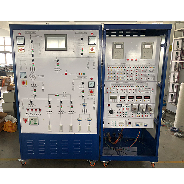
The power supply and distribution technology experimental device includes the following core components: primary wiring system of transformation station, measuring meter, multi-functional microcomputer protection device, compensation capacitor bank, short-circuit setting module, conventional relay, characteristic test signal system, etc.
The control power supply of the entire experimental system (including the relay auxiliary voltage) adopts a DC 24V power supply within the safe voltage. The experimental signals are required to be output in accordance with the secondary standards of the power system, and the output power is strictly controlled to eliminate the risk of electric shock.
(1) Primary wiring system of transformation and distribution station:
Analog 10kV/380V step-down transformer station, including at least 2 10kV incoming lines (one of which can be used as a backup power supply), 1 distribution transformer and 4 380V outgoing lines. A short-circuit fault setting unit is installed in the primary wiring system to simulate various fault conditions of lines or equipment.
Cont*ns at least 10 three-phase simulated circuit breakers: simulated with three-phase AC contactors. The analog circuit breaker can perform opening and closing operations through local manual buttons and remote remote control. The local button of the analog circuit breaker has red and green light indications (lighted button, red light means closing, green light means opening).
Virtual spectrum analyzer, logic analyzer, oscilloscope, three-meter simulation software:
This software is in apk format and can be used on PC or mobile terminals. The functions of this software are: resistance measurement, AC voltage measurement (measuring transformer, if the multimeter burns out when measuring the transformer, black smoke will emit prompts and can reset the multimeter), determine the polarity of the transistor, measure the DC voltage (the light turns on when the ammeter is turned on), measure the DC current, and determine the quality of the capacitor. This software can drag the red and black pen tips at will. When the two pen tips are dragged and positioned on the object to be measured, a red circle will be displayed. If the positioning is not accurate, no red circle will be displayed, and when incorrect operations are performed (such as the wrong range selected, If the measured data is wrong, etc.), the meter pointer will not respond, prompting errors and re-measurement, etc. This multimeter can select AC voltage gear, DC voltage gear, resistance gear, current gear, resistance adjustment to 0, and can enlarge the display data. Clearly view the measured data size. Students can learn the correct use of multimeters through this software.
(2) Multifunctional microcomputer protection device:
Requirements include the following devices:
10kV feeder microcomputer protection device module
35kV line microcomputer device module
110kV line group microcomputer protection device module
Transformer m*n protection device module
Transformer backup protection device module
Capacitor microcomputer protection device module
Motor microcomputer protection device module
Digital current relays, digital voltage relays, digital power directional relays, digital differential relays, digital impedance relays, digital inverse time current relays and other digital relay modules.
Supports automatic control functions such as automatic switching device and reactive power compensation device.
(3) Measuring meter:
Provide at least 5 pointer voltmeters to indicate the bus voltage.
(4) Compensation capacitor bank:
Provide at least 4 sets of low-voltage compensation capacitors and control circuits, which are required to be capable of manual compensation and automatic compensation controlled by the reactive power compensation device.
(5) Short circuit setting module:
It can meet various types of short circuit (single-phase to ground, two-phase short circuit, two-phase short circuit to ground, three-phase short circuit) fault operation.
(6) Conventional relay and characteristic test signal system:
Provide at least electromagnetic current relays, electromagnetic voltage relays, intermediate relays, and time relays.
Characteristic test signal system parameters: output voltage 0-220V adjustable, output current 0-10A adjustable, equipped with indicating instrument.
Practical tr*ning safety education virtual simulation software: This software is developed based on unity3d. The software adopts the form of three-dimensional roaming. Movement can be controlled by the keyboard and the lens direction can be controlled by the mouse. It is equipped with mechanical safety distance experiments, mechanical safety protection device experiments, and mechanical safety protection design basis. During the assessment, when the experiment is in progress, the three-dimensional roaming screen uses arrows and footprints to prompt the user to move to the experimental location. The circle around the mechanical object shows the working radius. The experimental process is accompanied by a dialog box reminder of the three-dimensional robot.
A. The content of the mechanical safety distance experiment includes the safety distance experiment to prevent upper and lower limbs from touching the danger zone (divided into two fence heights and opening sizes). After selecting to enter, GB23821-2009 "Mechanical Safety to Prevent Upper and Lower Limbs from Touching the Danger Zone" pops up in front of the camera. "Safe Distance" requirements, error demonstration: The experimental process is that after the human body enters the working radius of the mechanical object and is injured, the red screen and voice prompts that the human body has received mechanical damage, and returns to the original position and conducts the next experiment. The last step is the correct approach.
B. Mechanical safety protection device experiments are divided into safety interlock switches, safety light curt*ns, safety mats, safety laser scanners and other protection device experiments. Optional categories (safety input, safety control, safety output, others), manufacturers, products List (safety interlock switch, safety light curt*n, safety mat, safety laser scanner, safety controller, safety relay, safety guardr*l). There is a blue flashing frame reminder at the installation location. Experimental process: select the safety guardr*l and install it, select the safety interlock switch (or select the safety light curt*n, safety mat, safety laser scanner) and install it, select the safety controller and install it in the electrical control box , select the safety relay and install it in the electrical control box, click the start button on the electrical control box. If you enter a dangerous area, the system will sound an alarm and the mechanical object will stop working. Select the reset button on the electrical control box to stop.
C. The basic assessment of mechanical safety protection design requires the completion of the installation of the mechanical safety system, and the correct installation of safety guardr*ls, safety interlock switches, safety light curt*ns, safety mats, safety laser scanners, safety controllers, safety relays, 24V power supplies, signal lights and Emergency stop button, the assessment is divided into ten assessment points. Some assessment points have 3 options, which are freely chosen by the students. After selecting the final 10 assessment points, submit for confirmation, and the system will automatically obt*n the total score and the score of each assessment point. .
D. The software must be on the same platform as a whole and must not be displayed as separate resources.
E. At the same time, we provide customers with the VR installation package of this software to facilitate users to expand into VR experiments. VR equipment and software installation and debugging are not required.
(7) Microcomputer protection graphical programming software
Including but not limited to the following microcomputer protection and automatic device functions:
10kV line protection
35kV line protection
110kV line protection
Transformer m*n protection
Transformer backup protection
Motor protection
Capacitor protection
Prepare for self-investment
Generator protection
Reactive power compensation function
The graphical interface is consistent with the protection device, and the protection pressure plate, protection setting value, action realization, etc. can be set online.
Support data detection and status display functions
Supports read protection reporting function
Support reading SOE report function
Supports the function of reading wave recording data, and can save and open historical wave recording data.
Virtual multimeter parameters:
AC voltage ranges: 10, 50, 250, 1000
DC voltage range points: 0.25, 1, 2.5, 10, 50, 250, 1000
Ohm scale: x1, x10, 100, 1000, 1K, x10K, x100K
Ammeter gears: 50μa, 0.5, 5, 50, 500
BATT: 1.2-3.6V, RL=12Ω
BUZZ:R×3
Infrared emission detection function: vertical angle ±15°, distance 1-30cm
Transistor measuring hole
3. Practical tr*ning content
Factory shift and distribution room duty skills tr*ning
Experiment 1. Transformation, distribution, transmission and switching operation experiment
Experiment 2. Experiment on power outage and switching operation of power substation and distribution station
Experiment 3: Switching operation from one incoming power supply to two power supply lines
Experiment 4: Switching operation experiment from two incoming lines to one line power supply
Experiment 5. Transformer switching operation experiment from operation to m*ntenance
Experiment 6. Transformer m*ntenance to operation switching operation experiment
Experiment 7. Busbar running to m*ntenance switching operation experiment
Experiment 8: Busbar m*ntenance to operation switching operation experiment
Microcomputer protection experiment
Experiment 1. Simulation system short circuit experiment
Experiment 2. Microcomputer line protection parameter setting operation
Experiment 3, 6~10kV line overcurrent protection experiment
Experiment 4. Two-section line overcurrent protection experiment
Experiment 5. One-time reclosing experiment of power supply and distribution system
Experiment 6: Comprehensive experiment on line overcurrent protection and automatic reclosing
Experiment 7. Comprehensive experiment on line overcurrent protection and acceleration after automatic reclosing
Relay experiment
Experiment 1. Characteristics experiment of typical current relays
Experiment 2. Characteristics experiment of typical voltage relays
Experiment 3. Characteristics experiment of typical time relays
Experiment 4. Characteristics experiment of typical intermediate relays
Experiment 5. Characteristics experiment of signal relay
Experiment 6. Circuit breaker control and signal loop experiment
Automatic device tr*ning for power supply system
Experiment 1. Hand reactive power compensation and voltage regulation experiment
Experiment 2. Automatic reactive power compensation and voltage regulation experiment
Experiment 3. Incoming line preparation and automatic switching experiment
Experiment 4. Mother-link automatic switching experiment
 Wechat scan code follow us

24-hour hotline+86 18916464525

Phone18916464525
ADD:Factory 414, District A, No. 6, Chongnan Road, Songjiang Science and Technology Park, Shanghai ICP: Sitemap