Shanghai Daiyu Education Equipment Manufacturing Co., Ltd.
Language:


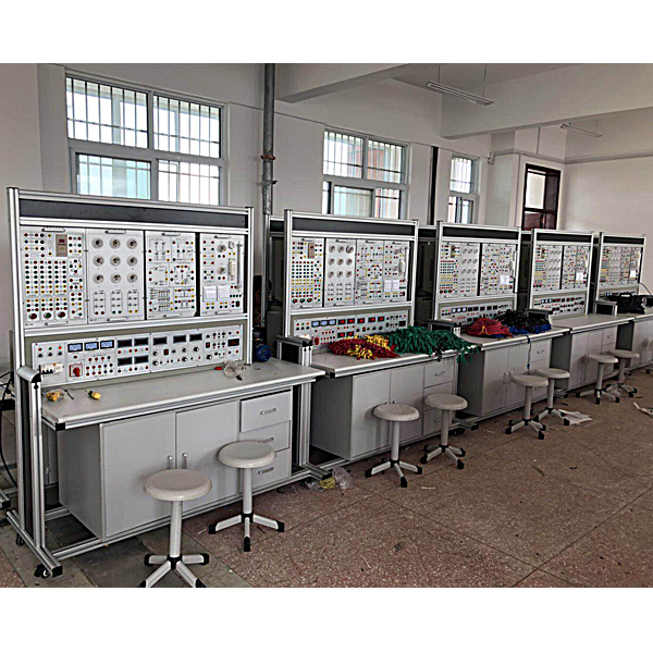


The electrical and electronic comprehensive experimental system absorbs the advantages of advanced teaching instruments at home and abroad, fully considers the current situation and future development trends of the laboratory , and innovates in terms of performance and structure. It adopts a hanging box structure, which is simple and clear, and has a reasonable layout. Easy and flexible to use. The experimental instruments have fully digital display and high precision. The power supply and instruments involved in the experiment are reliably protected. At the same time, a reliable personal safety protection system is set up. This experimental device has excellent performance and is the first choice for laboratories in major technical secondary schools. best choice.
2. Simulation experiment software:
1. Electricity safety and electric shock first *d virtual simulation system (demo and copyright certificate provided): The software uses a virtual screen that combines two-dimensional and three-dimensional to teach students the safety of electricity and first *d methods. The software has single-phase electric shock, two-phase electric shock, and two-phase electric shock first *d. Principles of electric shock, step-over electric shock, low voltage electric shock first *d, high voltage electric shock first *d, artificial respiration rescue method, holding hands breathing rescue method, chest heart compression rescue method, etc., single-phase electric shock rep*r live disconnection, rep*r socket electric shock, outdoor Demonstration of principles such as electric shock. The teaching of low-voltage electric shock and high-voltage electric shock m*nly expl*ns and demonstrates to students how to rescue people who are suffering from low-voltage electric shock or high-voltage electric shock. Artificial respiration rescue method, hand-holding breathing rescue method, and chest cardiac compression rescue method are demonstrated using 3D virtual simulation technology. After rendering and Polish it to make the model look like the real part and look realistic. Through practical tr*ning, students can be educated on the safe use of electricity in the tr*ning room, improve students' safety awareness, and enable students to learn some self-rescue methods, so that students can take cert*n safety measures to protect themselves when encountering danger, and become familiar with various Causes of electrical accidents and practical measures to deal with them to reduce the occurrence of electrical accidents.
2. M*ntenance of electricians, electronic motors and vocational qualification tr*ning assessment simulation software (providing demonstration and copyright certificate): The software content includes common sense of safe electricity use, electrician tools, electrician diagrams, electrician instruments, electrician lighting circuits, motors, transformers, low-voltage electrical appliances, Electric mops, oscilloscopes, low-frequency signal sources, welding processes, SMT technology, electronic product manufacturing processes, troubleshooting, wiring, three-dimensional disassembly and assembly of reducers, disassembly and assembly of shafting mechanisms (including cylindrical gear shafting, bevel gear shafting, worm shaft Department and more than ten experiments) and other modules, schools can select corresponding tr*ning modules for tr*ning according to students' learning progress.
3. Three-meter simulation software (demo and copyright certificate provided): This software is in apk format and can be used on PC or mobile terminals. The functions of this software are: measurement of resistance and measurement of AC voltage ( Measuring the transformer, if the multimeter burns out when measuring the transformer, black smoke will appear and the multimeter can be reset), transistor polarity judgment, DC voltage measurement (the light will turn on when the ammeter is turned on), DC current measurement, and capacitance is good. Bad judgment. This software can drag the red and black pen tips at will. When the two pen tips are dragged and positioned on the object to be measured, a red circle will be displayed. If the positioning is not accurate, no red circle will be displayed, and when incorrect operations are performed (such as the wrong range selected, If the measured data is wrong, etc.), the meter pointer will not respond, prompting errors and re-measurement, etc. This multimeter can select AC voltage gear, DC voltage gear, resistance gear, current gear, resistance adjustment to 0, and can enlarge the display data. Clearly view the measured data size. Students can learn the correct use of multimeters through this software.
4. Teacher teaching design system (providing demonstration and copyright certificate): This system is in apk format and can be used on PC or mobile. This system can set faults manually or automatically. This system has passed The green box in the circuit diagram selects manual setting of fault points (up to 39 fault points can be set), or the system can automatically set one random fault point, two random fault points, three random fault points, and four random fault points automatically. Fault point setting, five random fault point settings. This system has toolbox, component library, magnifying glass, circuit diagram and other functions. You can choose a multimeter for detection through the toolbox, select appropriate components through the component library, and you can clearly see through the magnifying glass. Understand the various components and circuits. This system allows students to understand the working principle and circuit structure of the motor star-delta start control circuit through the setting of faults in the motor star-delta start control circuit and various investigations.
2. Features:
1. Strong comprehensiveness. It integrates all experimental projects of basic electronic courses in various schools in China.
2. Strong adaptability. The depth and breadth of experiments can be flexibly adjusted according to needs, and popularization and improvement can be organically combined according to the teaching process. The device has a building block structure and is easy to replace. Add parts to expand functions or develop new experiments.
3. Strong complete set: Instruments, special power supplies, and special wires for experimental connections are all fully equipped. The performance, accuracy, and specifications of the instruments are closely combined with the needs of the experiment.
4. Strong consistency. Reasonable selection of experimental devices and complete supporting facilities ensure that multiple sets of experimental results have good consistency, making it easier for teachers to organize and guide experimental teaching.
5. Strong intuitiveness. This device adopts a structure that combines the whole with pendants. The power supply configuration and instruments are clear at a glance. The tasks of each experimental pendant are clear, and the operation and m*ntenance are simple.
3. Technical indicators and description:
1. Overall dimensions: 1600x700x1530mm
2. Working power supply: AC three-phase four-wire 380±5% 50HZ
3. Input power: <1.5KVA
4. Output AC power: three-phase four-wire 380V.
5. Personal safety protection functions: current-type leakage protection, voltage-type leakage protection and anti-electric shock experimental wires.
6. DC regulated power supply: two sets of 0--30V continuously adjustable, automatic relay shifting, digital meter display, automatic overload protection, indication and automatic recovery functions.
7. Constant current source: 0--200mA continuously adjustable, digital meter display, open circuit protection.
8. Power function signal generator (with frequency meter):
(1) Frequency range: 0.2Hz~2MHz, divided into seven levels
(2) Output waveform: sine wave, triangle wave, square wave, ramp wave, pulse wave, 50Hz sine wave (3) Duty cycle adjustment: 20% ~ 80%
(4) Scan rate: 10ms~5s.
(6) Output protection: short circuit protection, input voltage resistance ±35V (1 minute)
(5) Output voltage amplitude: 20VP-P (load 1MΩ), 10VP-P (load 50Ω), with output attenuation
(7) Frequency meter: six-digit LED display, external frequency measurement range: 0~50MHz, external frequency measurement sensitivity: 100mV
(8) Output amplitude indication: three-digit LED digital tube display
(9) With ≥10M power output.
(10) Virtual multimeter parameters: AC voltage range points: 10, 50, 250, 1000; DC voltage range points: 0.25, 1, 2.5, 10, 50, 250, 1000; Ohm range points: x1, x10 ,,100,,1000,,1K,x10K,x100K; Ammeter range: 50μa, 0.5, 5, 50, 500; BATT: 1.2-3.6V, RL=12Ω; BUZZ: R×3; Infrared emission detection function: Vertical angle ±15°, distance 1-30cm; triode measuring hole.
Features: All ports have short-circuit protection and anti-input voltage protection, dual display function (LED) for frequency and output amplitude, power output for convenient experimental teaching, built-in linear/logarithmic frequency sweep function and external frequency modulation function.
9. DC digital voltmeter: made by microprocessor; 0.5 level accuracy; measurement range: 0-300V.
10. DC digital milliammeter: made by microprocessor; 0.5 level accuracy; measuring range: 0-500mA.
11. DC digital ammeter: made by microprocessor; 0.5 level accuracy; measurement range: 0-5A.
12. AC digital voltmeter: produced by the latest professional MCU; accuracy level 0.5, measurement range: 0-450V.
13. AC digital ammeter: produced by the latest professional MCU; accuracy level 0.5, measurement range: 0-5A.
14. Intelligent power and power factor meter
Designed by 24-bit dedicated DSP, 16-bit high-precision AD converter and high-speed MPU unit, it realizes human-machine dialogue function control mode through key control and digital display window. The software adopts RTOS design ideas and is equipped with PC monitoring software to enhance analysis capabilities. Can measure the power and power factor of the circuit. The power measurement accuracy is level 1.0, the power factor measurement range is 0.3-1.0, the voltage and current range is 450V and 5A, and it can automatically identify the load properties (inductive display "L", capacitive display "C", pure resistance does not display), and can Store 15 sets of measurement data for review at any time.
15. Tr*ning connection cables: According to the characteristics of different tr*ning projects, two different specifications of tr*ning connection cables are equipped. Both strong and weak currents adopt a high-reliability sheath structure and a gun is used to plug the connection cables (there is no possibility of electric shock). The inside is made of oxygen-free copper to form h*r-thin multi-strand wires to achieve the purpose of ultra-softness. It is wrapped with a nitrile polyhexylene chloride insulation layer, which has the advantages of softness, high voltage resistance, high strength, anti-hardening, and good toughness. , the plug is made of solid copper parts coated with beryllium light copper shrapnel, making the contact safe and reliable; both wires can only match the sockets with corresponding inner holes and cannot be mixed, which greatly improves the safety and rationality of the tr*ning.
16. Experiment hanging box:
The schematic diagram and symbols are printed on the front panel of the experimental hanging box, and the corresponding components are welded on the reverse side. The parts that need to be measured and observed are equipped with locking connectors, which are easy to use, intuitive and reliable. The experimental circuit is designed in the unit circuit mode, and each The unit circuit is m*nly a basic circuit, and then different components are connected to the circuit parameters or different unit circuit combinations are used to complete different experimental requirements.
(1) Circuit basic experiment box (1)
Provides Kirchhoff's law (three typical fault points can be set), superposition principle (three typical fault points can be set), Thevenin's theorem, Norton's theorem, two-port network, reciprocity theorem, R, L, C series resonant circuit (L uses *r-core inductor), R, C series and parallel frequency selection circuit and first-order and second-order dynamic circuit experiments. All experimental devices are complete, the experimental units are clearly isolated, the experimental circuits are complete and clear, and the verification experiments and design experiments are combined.
(2) AC circuit experiment hanging box
Provides experiments on single-phase and three-phase load circuits, fluorescent lamps, transformers, mutual inductors and watt-hour meters. The loads are three completely independent lamp groups, which can be connected into Y or △ three-phase load lines. Each lamp group is equipped with three parallel incandescent lamp sockets (each group is equipped with three switches to control three loads. (on and off of the parallel branch), nine incandescent lamps below 60W can be inserted, and each lamp group is equipped with a current socket; the fluorescent lamp experimental device includes a 30W rectifier, capacitor (1uF/500V, 2.2uF/500V, 4.7uF/500V), Starter and short-circuit button; an iron core transformer (50VA, 36V/220V), with fuses and current sockets on both the primary and secondary sides; a set of mutual induction coils, which can adjust the distance between the two coils and The small coil is placed inside the large coil, equipped with one large and one small iron rod and one non-magnetic aluminum rod; an electric meter with specifications of 220V, 3/6A. It is temporarily hung up during the experiment, and its power cord , load lines have been connected to the terminals of the electric meter wiring frame, making the experiment convenient; a 220/8.2V (0.5A)/8.2V (0.5A) transformer can be used to judge the primary and secondary windings of the transformer with the same terminals. Experiments on the identification of identical terminals of double windings on the secondary side of a transformer and its application in transformers.
(3) Component box
It is equipped with several experimental components such as resistors, capacitors, diodes and a 0-99999.9 ohm/2W resistance box required for the experiment.
(4) Controlled source and gyrator hanging box
It is equipped with VCVS, VCCS, CCVS, CCCS controlled source experimental circuits, gyrator experimental circuits, and negative impedance converter experimental circuits.
(5) Analog electronic experiment hanging box
It is equipped with power supply experimental circuit, operational amplifier experimental circuit, DC signal source, low-voltage AC power supply, resistor and capacitor triode and other experimental components; equipped with single-tube, multi-stage, negative feedback experimental modules, separation and integrated power amplification experimental modules.
(6) Digital electronic experiment hanging box
Equipped with 8-bit logic level switch, 8-bit logic level indicator, four-digit decimal coding display, a common cathode digital tube, two sets of dial switches, single pulse, high-reliability round-pin integrated socket 8P, 14P, 16P , 28P, 40P, etc., as well as resistors, potentiometers, transistors, etc. required for experiments.
4. Equipment configuration
1. Experimental table: aluminum wood structure, wear-resistant and fireproof panel, equipped with drawers and cabinets for storing tools, accessories, etc.
2. Power control panel: includes AC and DC digital voltage and current power factor meters, DC regulated power supply; constant current source, signal source, AC three-phase power supply, and AC low-voltage power supply.
3. 1 set of experimental wires, experimental instructions, and instruction manual.
5. Experimental projects
Electrical Experimental Project
1. Use of basic electrical instruments and calculation of measurement errors
2. Methods to reduce instrument measurement errors
3. Ohm’s law
4. Series, parallel and mixed circuits of resistors
5. Resistor divider circuit
6. Series, parallel and mixed circuits of capacitors
7. Capacitor charging and discharging circuit
8. Measure resistance by voltammetry
9. Node voltage method
10. Loop voltage method
11. Branch current method
12. The relationship between resistance and temperature: Use voltammetry to measure the resistance of the filament at different voltages.
13. Extension of voltmeter range
14. Extension of ammeter range
15. Volt-ampere characteristics of circuit components
16. Inspection of DC resistance circuit faults
17. Measurement of potential in circuits
18. Kirchhoff’s voltage law
19. Kirchhoff’s current law
20 Superposition principle for measuring external characteristics of voltage source
21. Superposition principle
22. Equivalent transformation of voltage source and current source
23. Conditions for the load to obt*n maximum power
24. Thevenin’s theorem
25. Norton’s theorem
26. Reciprocity theorem
27. Two-port network
28. Double switch two-place control
29. RLC series AC circuit
30. RLC parallel AC circuit
31. RLC series resonant circuit
32. Characteristics of inductors and capacitors in DC and AC circuits
33. RL and RC series circuit in sinusoidal steady state
34. Connection of fluorescent lamp circuit
35. Methods to improve power factor
36. Electromagnetic induction phenomenon
37. Mutual inductance coupling circuit
38. Judgment of the same terminal of the mutual induction coil
39. Research on the transition process of first-order circuits
40. Research on the transition process of second-order circuits
41. Single-phase transformer
42. Transformer parameter measurement and winding polarity identification
43. Measurement of AC circuit parameters
Analog circuit experimental project
1. Use of commonly used electronic instruments
2. Simple test of diode
3. Experiment on input and output characteristics of transistor
4. Single-stage amplifier circuit
5. Two-stage amplifier circuit
6. Negative feedback amplifier circuit
7. Emitter follower
8. Differential amplifier circuit
9. Field effect tube amplifier
10. RC sine wave oscillation circuit
11. LC oscillator and frequency selective amplifier
12. Basic parameter testing of integrated operational amplifier
13. Integrated operational amplifier proportional summing circuit
14. Integrated operational amplifier integral and differential circuits
15. Voltage comparator circuit with integrated operational amplifier
16. Waveform generator
17. Active filter
18. Integrated power amplifier
19. Complementary symmetric power amplifier
20. Integrated voltage regulator
21. Series voltage stabilizing circuit
22. Thyristor controlled rectifier circuit
Digital circuit experimental project
1. Transistor switching characteristics, limiter and clamp
2. Logic function and parameter testing of TTL integrated logic gates
3. Logic function and parameter testing of CMOS integrated logic gates
4. Connection and driving of integrated logic circuits
5. Design and testing of combinational logic circuits
6. Decoder and its application
7. Data selector and its application
8. Triggers and their applications
9. Counters and their applications
10. Shift register and its applications
11. Pulse distributor and its application
12. Use gate circuit to generate pulse signal - self-excited multivibrator
13. Monostable trigger and Schmitt trigger - pulse delay and waveform shaping circuit
14. 555 time base circuit and its applications
Recommended products: Electrician tr*ning bench
 Wechat scan code follow us

24-hour hotline+86 18916464525

Phone18916464525
ADD:Factory 414, District A, No. 6, Chongnan Road, Songjiang Science and Technology Park, Shanghai ICP: Sitemap