DYLR-M0 Visual Refrigeration Cycle Demonstration Training Device
Release time:2024-06-17 22:00viewed:times
1. Overview:
Suitable for teaching majors such as refrigeration , *r conditioning, food freezing, and home appliances
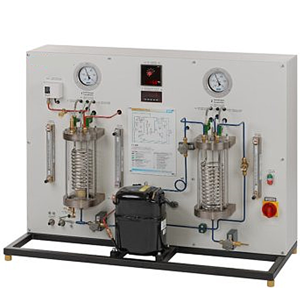
. The compressor, evaporator, and condenser in the system use transparent pressure-resistant glass as the shell, which can directly observe the evaporation and condensation of the refrigerant, and the refrigeration effect can be observed through the changes in the inlet and outlet water temperatures. 2. M*n features:
1. Refrigerant: The evaporation and condensation of the refrigerant outside the spiral evaporator and condenser tubes can be observed through the glass condenser and evaporator.
2. Glass condenser (refrigerant goes outside, water goes inside the evaporator tube), the condensation process of the refrigerant in the glass condenser and the working phenomenon of the compressor can be observed through the glass.
3. Glass evaporator: (refrigerant goes outside, water goes inside the evaporator tube) The evaporation process of the refrigerant in the glass evaporator and the working phenomenon of the compressor can be observed through the glass.
3. M*n configuration:
Experimental device: It consists of a refrigeration system, temperature test, flow measurement, and control system.
1. Temperature measurement:
it can measure the suction pressure, exhaust pressure, pressure, suction temperature, exhaust temperature, inlet temperature, and indoor ambient temperature.
2. Control panel:
the panel adopts a double-layer color spray structure with novel shape; the refrigeration system is arranged on the panel, which can intuitively display the structure of the refrigeration system; the front is equipped with a power control and measuring instrument function panel.
3. Module:
measure the compressor power separately. The intelligent control mode of human-computer dialogue is realized through key control and digital display window, and the active power, reactive power, power factor, voltage, current, frequency and load properties of the load can be measured;
1) It has 6 major protection functions: short circuit, overcurrent, overvoltage, undervoltage, loss of pressure, and power limitation; the power supply has a one-button locking function to prevent the leakage protector from closing when handling faults, causing electric shock hazards; the power supply has a fault locking function. When a fault occurs and the circuit breaker trips, it cannot be powered on manually. It can only be powered on successfully after clearing the fault.
2) The LCD panel is used to monitor the operation of the equipment in real time, and the voltage, current, power, electric energy and other parameters can be monitored in real time. The LCD touch screen monitors the values.
3) Threshold value equipment: short circuit, overcurrent, overvoltage, undervoltage, loss of pressure, power and other threshold settings
4) Short circuit protection: When the current of the protection equipment is 3 times larger than the same, it will trip instantly within 0.3 seconds
5) Leakage protection: When the leakage value reaches 1% of the set value, the system will be instantly powered off within 0.1 seconds.
Overload protection: Prevent equipment from catching fire. When the load reaches 5% of the set value, the system will trip instantly within 0.1 seconds.
6) Overvoltage protection: Effectively prevent equipment damage. When the voltage reaches 270V, the system will trip instantly within 0.5 seconds.
7) Undervoltage protection: Effectively prevent equipment damage. When the voltage reaches 165V, the system will trip instantly within 0.5 seconds.
8) Forced fault locking function: When a fault occurs and causes tripping, it is impossible to power on manually. The power can only be successfully powered on after clearing the fault.
9) Fault query: One-key fault can query the historical fault source
10) Fault test function: The unsafe power consumption function in the system can be tested online, and the fault source can be eliminated with one-key fault query
11) Manual and automatic function: manual and automatic free switching
4. Refrigeration system:
compressor, glass condenser, sight glass, dry filter, manual throttle valve, quartz glass evaporator; refrigerant: 600A,
5. Secondary circulation system: flow rate 1 ton, head 9 meters, flow meter: 4-90L/h;
6. Organic water tank: 30×20×30cm;
7. Dimensions: 1000×700×800mm Working voltage: 220V Power: 500W
8. Virtual multimeter parameters:
AC voltage range: 10, 50, 250, 1000
DC voltage range: 0.25, 1
, 2.5, 10, 50, 250, 1000 Ohm range: x1, x10, 100, 1000, 1K, x10K, x100K
Amperemeter range: 50μa, 0.5, 5, 50
, 500 BATT: 1.2-3.6V, RL=12Ω
BUZZ: R×3
Infrared emission detection function: vertical angle ±15° distance 1-30cm
transistor measurement hole
9. Glass condenser 1:
10. Glass evaporator 1
11. Spiral heat exchanger 2
12. Single chip microcomputer , PLC programmable design and control virtual simulation software:
This software is developed based on Unity3D, with built-in experimental steps, experimental instructions, circuit diagrams, component lists, connection lines, power on, circuit diagrams, scene reset, return and other buttons. After the connection and code are correct, the 3D machine model can be operated through the start/stop, forward motion, and reverse motion buttons . When the line is connected, the 3D machine model can be enlarged/reduced and translated.
1. Relay control: Read the experimental instructions and enter the experiment. By reading the circuit diagram, select relays, thermal relays, switches and other components in the component list and drag and drop them into the electrical cabinet. The limiter is placed on the 3D machine model. You can choose to cover the lid. Some component names can be renamed. Then click the connection line button to connect the terminals to the terminals. After the machine circuit is successfully connected, choose to turn on the power and operate. If the component or line connection is wrong, an error box will pop up, and the scene can be reset at any time.
2. PLC control: The experiment is the same as relay control, with the addition of PLC control function. After the connection is completed, enter the program writing interface through the PLC coding button, write two programs, forward and reverse, with a total of 12 ladder diagram symbols. After the writing is completed, select Submit for program verification. After the verification is successful, turn on the power to operate. Components, line connections, and code errors will pop up prompt error boxes, and the scene can be reset at any time.
3. Single-chip microcomputer control: The experiment is the same as relay control, with the addition of single-chip microcomputer control function. After the connection is completed, enter the programming interface through the C coding button, enter the correct C language code, and submit the verification successfully. Turn on the power to operate. Components, line connections, and code errors will pop up prompt error boxes, and the scene can be reset at any time.
IV. Tr*ning functions:
1. Carry out refrigeration cycle process and demonstration,
3. The evaporation process and working phenomenon of the refrigerant can be observed through the glass
4. The condensation process and working phenomenon of the refrigerant can be observed through the glass
3. Common faults of the refrigeration system can be demonstrated
4. The circulation principle of the water system can be demonstrated
5. Recognize the role and structural style of multiple throttle valves in the refrigeration system
6. Study the principle of refrigerant reflux heat pump in the refrigeration system.
8. Use of manual expansion valve


 Wechat scan code follow us
