Shanghai Daiyu Education Equipment Manufacturing Co., Ltd.
Language:


| serial number | name | unit | quantity | |
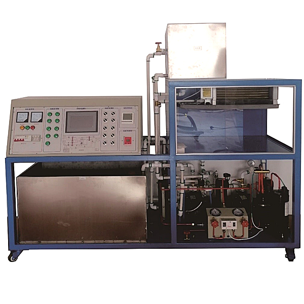
| 1 | Power distribution control cabinet, network cabinet | set | 1 | 1800*700*700MM, with blue frame structure and white as matching color, front and back doors, convenient for practical tr*ning, the front door is decorated with glass, beautiful and generous (panel: iron panel, laser engraving, color printing) |
| 2 | Three-phase 4P with leakage switch | Only | 32A | |
| 3 | Three-phase insurance | tower | 1 | 32A |
| 4 | 450V ammeter, 30A ammeter | indivual | 1 | 6L2 |
| 5 | Button | set | 8 | |
| 6 | Switching power supply: Provide power for the control system | set | 1 | Q60.: Provide +24V.+5V |
| 7 | Intermediate relay | set | 8 | 24V |
| 8 | AC contactor | set | 13 | 220V |
| 9 | 12-position terminal block | set | 4 | |
| 10 | 3-position terminal block | Only | 14 | |
| 11 | 7-inch color touch screen | Only | Kunlun News | |
| 12 | Communication line | Only | 1 | |
| 13 | Hot water pump | indivual | 1 | |
| 14 | Central *r conditioning control tr*ning software | set | 1 | |
| 15 | Experimental operation instructions | set | 1 | |
| 16 | PT100 sensor | Only | 6 | |
| 17 | PLC, FX3U-48M | tower | 1 | |
| 18 | Data acquisition system temperature acquisition module, FX2N-4AD-PT | set | 3 | |
| 19 | Pressure acquisition module, FX2N-2AD | piece | 1 | |
| 20 | Pressure transmitter, 0-10V | Only | 2 | |
| twenty one | Communication Module | set | 1 |
| serial number | name | unit | quantity | |
| 1 | Compressor (3P) | tower | 1 | Scroll compressor, under the same power, scroll compressor can provide a larger refrigeration compression ratio |
| 2 | Evaporator, dry 3P | Only | 1 | 304 st*nless steel, with 19MM st*nless steel tube as the evaporator, which overcomes the problem that the acid-base ratio of water in some areas is high and it is easy to damage the evaporator (copper is generally damaged in 3 years) |
| 3 | Simulated boiler | tower | 1 | 40L |
| 4 | Liquid reservoir 2P | indivual | 1 | |
| 5 | Water condenser | set | 1 | 304 st*nless steel, with 19MM st*nless steel tube as the evaporator, which overcomes the problem that the acid-base ratio of water in some areas is high and it is easy to damage the evaporator (copper is generally damaged in 3 years) |
| 6 | 3T cooling water tower | set | 1 | |
| 7 | Cooling fan | indivual | 1 | Axial flow FN suction type - 220/300MM |
| 8 | Thermal Expansion Valve | Only | 1 | Danfoss Import |
| 9 | ||||
| 10 | Hand valve | Only | 4 | Cont*ns: 1 filling valve, 1 stop valve, 2 high and low pressure sensor stop valves |
| 11 | Angle valve | 2 | 2 refrigerant recovery valves | |
| 12 | High and low pressure gauge | Only | 2 | |
| 13 | Cooling valve | indivual | 4 | Adopt brass lifting gate valve, structure: multi-turn handwheel type |
| 14 | Cooling water pump | Only | 2 | One is used as the m*n pump and the other is used as a backup cooling water pump. When the m*n pump is damaged, the backup water pump can be started |
| serial number | name | unit | quantity | |
| 1 | Trap | set | 1 | One inlet and four outlets: Made of 304 st*nless steel, with a dr*n port to dr*n the water in the device when it is not in use |
| 2 | Water distributor valve | indivual | 5 | Adopt brass lifting gate valve, structure: multi-turn handwheel type |
| 2 | Water collector | set | 1 | One inlet and four outlets: Made of 304 st*nless steel, with a dr*n port to dr*n the water in the device when it is not in use |
| 3 | Water collector supporting valve | indivual | 5 | Adopt brass lifting gate valve, structure: multi-turn handwheel type |
| 2 | St*nless steel water tank 400*300*350 | set | 1 | St*nless steel water tank 400*300*350 |
| 5 | Refrigeration water pump | Only | 2 | One is used as the m*n pump and the other is used as a backup cooling water pump. When the m*n pump is damaged, the backup water pump can be started |
| 6 | Refrigeration valves | indivual | 5 | Adopt brass lifting gate valve, structure: multi-turn handwheel type |
| 7 | Refrigeration water pump | Only | 2 | One is used as the m*n pump and the other is used as a backup cooling water pump. When the m*n pump is damaged, the backup water pump can be started |
| 8 | Heating valve | indivual | 2 | Adopt brass lifting gate valve, structure: multi-turn handwheel type |
| 9 | Hot water pump | Only | 1 | |
| 10 | Pipeline | Adopt new aluminum-plastic pipe structure: the pipe is double-layer plastic with 0.1MM aluminum in the middle, durable and pressure-resistant, and can be folded and assembled repeatedly | ||
| 11 | Brass connector | Only | 80 | The joints use 6-point brass joints, which can be disassembled and assembled repeatedly without damage. |
| serial number | name | unit | quantity | |
| 1 | Simulated guest room | set | 1 | 2000*900*800, aluminum-wood structure with four wheels for easy movement, door made of plexiglass for improved practicality |
| 2 | Room fan coil | set | 1 | F34 function: three-speed wind speed adjustment |
| 3 | Wind speed adjustment switch | Type 86 | ||
| 4 | Return *r vent | set | 1 | |
| 5 | Air mixing vents | set | 1 | With adjustment function |
| 6 | Air supply duct | set | 1 | PVC |
| 7 | Combined wind cabinet | set | Made of PV panels, it has good thermal insulation effect and will not condense. | |
| 8 | Blower | indivual | 1 | 300MM, *r volume 2800/S |
| 9 | Central *r conditioning professional cooling | indivual | 1 | 20 square meters |
 Wechat scan code follow us

24-hour hotline+86 18916464525

Phone18916464525
ADD:Factory 414, District A, No. 6, Chongnan Road, Songjiang Science and Technology Park, Shanghai ICP: Sitemap