Shanghai Daiyu Education Equipment Manufacturing Co., Ltd.
Language:


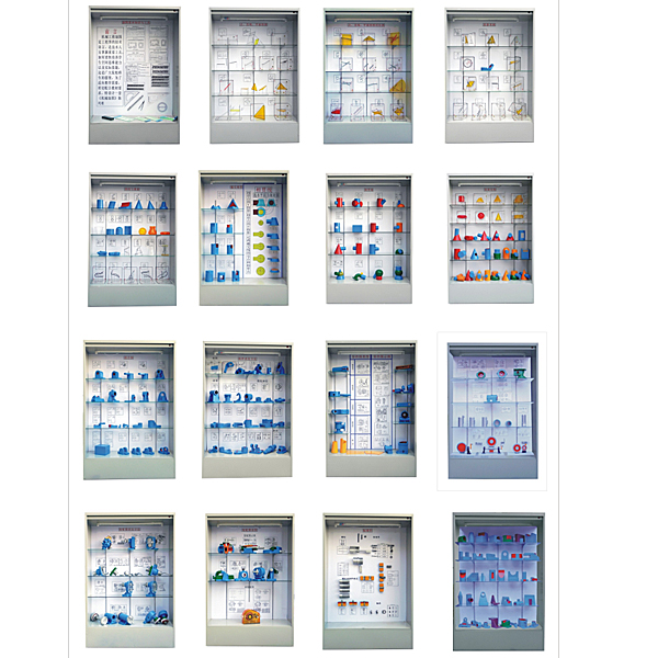


| Serial number and name | Display case contents |
| Cabinet No. 1: Basic knowledge and tools of drawing | 1. List of Roman numerals, 2. Example of Arabic numerals, 3. Example of Latin letters, 4. Title block, det*l column, 5. Proportion, 6. Basic requirements for font (GB-T 14691-93), 7. Long imitation of Song Dynasty Examples of Chinese characters, 8. Drawing format and size, 9. Drawing frame format, 10. Triangular ruler, 11. Triangular scale, 12. Circular protractor, 13. Multifunctional template, 14. Compass |
| The second cabinet: point, str*ght line, plane projection | 1. The three-sided projection of a point, 2. The three-sided projection of a str*ght line at a general position, 3. The real length of the line segment and the inclination angle α, 4. The vertical side, 5. The horizontal plane, 6. Oblique projection and orthographic projection, 7. Trace points of the str*ght line, 8. Characteristics of plane projection, 9. Trace plane, 10. Center projection method, 11. Projection characteristics of points on str*ght lines, 12. Projection characteristics of line segments, 13. Projection of four midpoints of angles |
| The third cabinet: relative positions of points, lines, and planes | 1. The right angle projection theorem, 2. The projection of two intersecting str*ght lines, 3. Use the accumulation property of projection to find the penetration point of the str*ght line and the plane, 4. Use the auxiliary surface method to find the penetration point of the str*ght line and the plane, 5. Use the accumulation property of projection Find the intersection line of two planes, 6. Plane trace method, 7. Projection of a circle on a normal vertical surface, 8. Analysis of the relative position of str*ght lines and projections on a three-dimensional surface, 9. Projection of two intersecting str*ght lines, 10. Intersection The projection characteristics of two str*ght lines, 11. Use the auxiliary line method to find the penetration point of the str*ght line and the plane, 12. Find the intersection line of two general position planes, 13. The projection of two parallel str*ght lines, |
| Cabinet 4: Projection Transformation |
1. Two basic methods of projection transformation (surface changing method), 2. Two basic methods of projection transformation (rotation method), 3. Rotation of points around the positive vertical axis, 4. Transformation of general position str*ght lines into new projection surface vertical lines , 5. Rotate the general position str*ght line into a parallel line on the projection surface, 6. Transform the general position str*ght line into a parallel line on the new projection surface, 7. Transform the general position plane into a parallel surface to the new projection surface, 8. Transform the general position plane into a new projection surface vertical plane, 9. Transform the normal vertical plane into a plane parallel to the projection plane, 10. Secondary change of planes of the point, 11. The parallel line of the projection plane becomes a vertical line of the projection plane, 12. Find the distance from point A to plane P and Point A is on the P plane. 13. The vertical foot K of the vertical line drawn. 14. Use the quadratic surface change method to draw the combined body view. |
| Cabinet Five: Curves and Surfaces |
1. Example of two-sided projection of a curved solid surface (oblique cylinder), 2. Example of two-sided projection of a curved solid surface (oblique cylinder), 3. Example of two-sided projection of a curved solid surface, 4. Example of two-sided projection of a curved solid surface (there are four in the upper left corner) 1/3 cylindrical groove), 5. Example of two-sided projection of a curved solid surface (oblique cone), 6. Example of two-sided projection of a curved solid surface (oblique cone), 7. Example of two-sided projection of a curved solid surface (upside-down cone) truncated cone), 8. Example of two-sided projection of a curved solid surface (a semi-cylinder with half a frustum groove), 9. Example of two-sided projection of a curved solid surface (a cylinder with a hemispherical groove), 10. Example of two-sided projection of a curved solid surface (combined rotation Body example 1), 11. Example of two-sided projection of a curved solid body (Example 2 of a combined rotary body), 12. Intersection line of the connecting rod head, 13. Projection of the intersection line of a sphere cut by a vertical plane, 14. Curve Formation, 15. Space curve, 16. Formation and projection of the surface of revolution, 17. Conical surface, 18. Cylindrical surface, 19. Conical surface, 20. Cylindrical spiral, 21. Conical spiral, 22. Single-leaf hyperbola Surface of revolution, 23. Formation of torus, 24. Intersection line of thimble, |
| Cabinet Six: Intersection and Intersection | 1. The projection of the hemispherical grooving, 2. The notched triangular pyramid, 3. The projection of the cylindrical grooving, 4. The projection of the grooving hollow cylinder, 5. 2 pieces of intersection lines, 6. The projection of the boring bar head , 7. Joint projection, 8. Jack cover projection, 9. 5 sections of phase inertial line, |
| Cabinet Seven: Intersecting Lines |
1. The intersection line of two orthogonal cylinders, 2. The intersection line of two orthogonal cylinders, 3. Use the spherical method to find the intersection line of the cylinder and the cone, 4. The intersection line of two orthogonal cylinders, 5. Drilling on the cylinder hole and the intersection line of two cylindrical holes, 6. The intersection line of the drilled hole in the cylinder and the two cylindrical holes, 7. The intersection line of two offset cylinders, 8. The intersection line of the truncated cone and the hemispherical sphere, 9. The intersection line of a cylinder and a cone that is orthogonal, 10. The intersection line of two cylinders obliquely, 11. The cylinder and the cone are orthogonal, 12. The intersection line of two cylinders with non-intersecting axes and unequal diameters, 13. Cylinder Intersecting with a hemispherical sphere, 14. 2 special cases of intersecting lines, 15. Intersecting lines of cylinders, truncated cones and spheres, |
| Cabinet Eight: Surface Intersection Line | 1. The projection of the column and the point selection on the surface, 2. The projection of the cone and the selection of points on the surface, 3. The projection of the prism and the selection of points on the surface, 4. Analysis of the midplane of the body, 5. The projection of the sphere and the selection of points on the surface. , 6. Ring projection and finding points on the surface, 7. Projection using a washer, 8. Cone projection and finding points on the surface, 9. 22 surface intersection models |
| Cabinet 9: Combination | 1. Do not draw lines at flush locations. 2. Shapes are close to each other. 3. Lines should be drawn at intersections. 4. Do not draw lines at tangent locations. 5. Bearing seat. 6. Bearing seat. 7. Bearing seat. 8. Support. Seat, 9. Bracket, 10. Bearing seat, 11. Shift fork, 12. Oblique section view, 13. Support, 14. Support, 15. Support (4 pieces) |
| Cabinet 10: Mechanical Expression Method | 1. The prescribed configuration of the six basic views, 2. Partial view of the compression rod, 3. View of the bracket, 4. Rotation view, 5. View, 6. Partial view, 7. View, 8. Remove section view, 9 , Half view, 10. Overlapping section, 11. Simplified drawing method (3 pieces), 12. Full section view of compound section (2 pieces), 13. Full section view of rotated section, 14. Compound section, 15. Full section view, 16. Compound section, 17. Oblique section view 18. Oblique section (2 pieces), 19. Step section (2 pieces), 20. Full section view of step section, 21. Section (2 pieces) |
| Cabinet 11: Parts Diagram |
1. Piston sleeve, 2. Pump shaft, 3. End cover, 4. Bracket, 5. Box, 6. Worm gear reduction box, 7. Valve body, 8. Flange, 9. Conical tube, 10 , Cylinder block, 11. Handwheel, 12. Axle frame, 13. Bracket, 14. Lathe t*lstock hollow sleeve plate |
| Cabinet 12: parts diagram, gears, keys, springs |
1. Spur gear transmission , 2. Bevel gear transmission, 3. Worm gear transmission, 4. Involute spline connection drawing method, 5. Ordinary flat key, 6. Semicircular key, 7. Cylindrical pin, 8. Pump Shaft, 9. Pump body 2 pieces, 10. Compression spring, 11. Tension spring, 12. Torsion spring, 13. Shell, 14. Support |
| Cabinet Thirteen: Assembly Drawing Expression Method |
1. Ball valve (2 pieces), 2. Oil pump, 3. Gear oil pump (2 pieces), 4. Milling cutter head (2 pieces), 5. Oil pump 1 (2 pieces), 6. Oil pump 2 (2 pieces), |
| Cabinet 14: Reading assembly drawings |
1. Sliding bearing, 2. Gear pump, 3. Cock, 4. Lever, 5. Micro-action mechanism, 6. Machine vise, 7. Bench vise, 8. Reducer |
| Cabinet 15: Standard parts |
1. Processing internal threads, 2. Drawing method of threaded connection, 3. Bolt connection, 4. Screw connection, 5. Double-ended stud connection, 6. Hexagonal head bolt, 7. Double-ended stud, 8. Slotted cylinder Head screws, 9. Slotted countersunk head screws, 10. Slotted pan head screws, 11. Slotted flat end set screws, 12. Type I hexagonal nuts, 13. Flat washers, 14. Spring washers, |
| Cabinet 16: Exercise Model | Total: 35 pieces (including; supports, intersecting lines, bearing seats, etc.) |
 Wechat scan code follow us

24-hour hotline+86 18916464525

Phone18916464525
ADD:Factory 414, District A, No. 6, Chongnan Road, Songjiang Science and Technology Park, Shanghai ICP: Sitemap