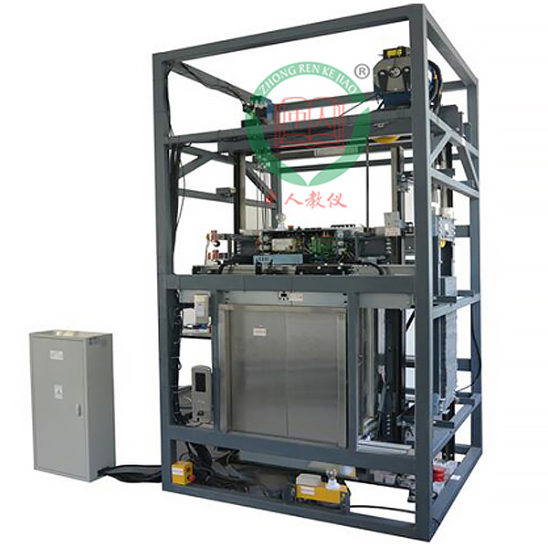
DYDT-KP elevator installation experimental platform
Release time:2024-06-28 05:30viewed:times
1. Scope of supply
1.1 Equipment name: Tr*ning teaching elevator
1.2 Quantity: one set
2. M*n technical parameters and performance requirements of the equipment
2.1 Basic requirements
▲2.1.1. The elevator installation and m*ntenance tr*ning device must have real elevator components including: traction drive system, car counterweight device, door opening and closing system, guidance system, and mechanical safety protection device.
2.2.2 The elevator parts, such as door machines, speed limiters, safety clamps, and limit switches, are the same as those of actual elevators. The elevator control operating system is the commonly used actual elevator control system such as Monarch, Blue Light, New Time, and Invt.
2.1.3 Requirements to meet the requirements of national tr*ning assessment. The software system has database management functions such as question bank management, random test paper generation, automatic time limit timing, automatic test paper scoring, automatic record archiving, statistics, query, summary report, file creation and archiving;
2.2 Technical requirements
2.2.1 The system software should at least have the assessment function, automatic test paper generation function, test timing function, automatic assessment scoring function, student information management function, student database management function, student information import and export function, database m*ntenance function, and backup database function.
2.2.2. The system adds an additional fault control system to realize the simulation of elevator fault status without affecting the elevator control system;
2.2.3 Virtual simulation system for comprehensive integrated tr*ning of vocational skills The model
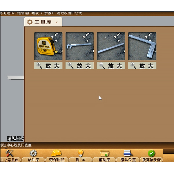
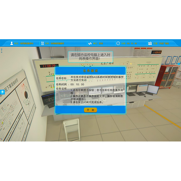
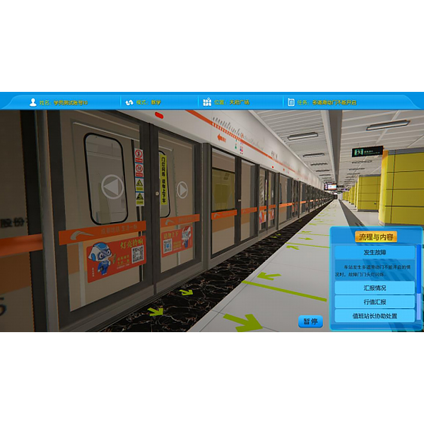
in the software can be rotated 360°, enlarged, reduced, and translated, and has universal interactive buttons: return, home page, and help. There are prompts for all virtual simulation task processes, and the software automatically ticks after completing a task. There is an experimental task 1 above the tool library, Basic Solid ( the XYZ space coordinate icon automatically rotates with the model when rotating.) A. Plane Solid: The experimental steps are divided into experimental tasks (text prompt tasks) - Build model (drag the model in the tool library to the three-projection surface system, and the projection will be automatically displayed. There will be prompts when the selection is wrong) - Change posture (change by clicking the up, down, left and right arrows) - Select projection (enter the answer interface, and select the three-dimensional projection diagram completed at this time from the 6 items) B. Cut Solid: The experimental steps are divided into experimental tasks (text prompt tasks) - Build model (drag the model in the tool library to the three-projection surface system, and the projection will be automatically displayed) - Mark the projection situation (mark the three-dimensional projection diagram, and select the corresponding marking symbol in the 14 blank columns) C. Intersecting solids: The experimental steps are divided into experimental tasks (text prompt tasks) - digging holes (select any digging hole model, then you can select any surface in the XYZ space coordinates, the models will switch at the same time, and a coordinate slider will appear. According to the displacement of the slider, the model will have a corresponding degree of cross-section) - aperture change (select 1-4 apertures) - rear through hole - select projection (enter the answering interface, and select the completed three-dimensional projection diagram at this time in 8 items) 2. Assembly A. Assembly assembly: The experimental steps are divided into experimental tasks (text prompt tasks) - select the assembly model (8 models can be selected) - assemble the assembly (select the tool library model according to the selected model and drag and drop the assembly) - section the assembly (you can select any surface in the XYZ space coordinates, the models will switch at the same time, and a coordinate slider will appear. According to the displacement of the slider, the model will have a corresponding degree of cross-section) - select side projection (enter the answering interface, based on the known front and horizontal projection diagrams, select the correct side projection diagram in 3 items) B. Assembly drawing reading: The experimental steps are divided into experimental tasks (text prompt tasks) - select the assembly section view (8 types of drawings can be selected) - build the assembly model (select the tool library model according to the selected model and drag and drop the combination) - cut the assembly (you can select any surface in the XYZ space coordinates, the model will switch at the same time, and a coordinate slider will appear. According to the displacement of the slider, the model will appear with a corresponding degree of section) - select the left view (enter the answer interface, according to the known m*n view and top view, select the correct left view from the 3 items) 3. Assembly A. Mechanical transmission mechanism : 8 mechanisms (worm gear, gear rack, spiral transmission, plane external meshing gear, plane internal meshing gear, space spur bevel gear, belt drive , ch*n drive) are optional. After selecting, the model will appear in the toolbar. Drag the model freely to combine. After the combination is completed, the model can be operated. Each mechanism comes with an introduction, video demonstration, and drawing method. There are 6 questions in the answer interface, and each question has 4 options. B. Gear oil pump: Select the tool library model according to the prompts and build the model step by step. You can choose to learn the introduction, drawing method, and animation principle (the internal movement principle of the model can be visualized). There are 2 questions in the answering interface, and each question has 4 options. C. Mechanical mechanism construction: 2 mechanisms (2-DOF robotic arm, 3-DOF robotic arm), select the tool library model according to the prompts and build the model step by step. After the combination is completed, the model can be operated. Each mechanism has an introduction and video demonstration. There are 2 questions in the answering interface (both models must be built before entering) and each question has 4 options. 2.3 Det*led configuration requirements 2.3.1 Overall dimensions: length x width x height 1450x1450x3000mm. 2.3.2 1 set of car and counterweight guide shoes. 2.3.3 1 permanent magnet traction machine. 2.3.4 1 set of car. 2.3.5 1 set of counterweight. 2.3.6 1 leveling sensor. 2.3.7 6 operating limit switches. 2.3.8 Door machines 2 sets. 2.3.9 Car doors and hall doors 2 sets. 2.3.10 Elevator control cabinet 1 set. 2.3.11 Car door controller 1 set. 2.3.12 Internal and external call buttons 1 set. 2.3.13 Operating landing station displays 2 sets. 2.3.14 Guide pulley and return pulley 1 set.
2.3.15 1 set of steel wire and rope end combination.
2.3.16 1 safety clamp.
2.3.17 1 speed limiter.
2.3.18 1 speed limiter hammer trigger switch.
2.3.19 1 buffer.
2.3.20 1 set of Siemens programmable controller.
2.3.21 4 relay boards.
2.3.22 1 fault control box.
2.3.23 elevator full load and weighing device.


 Wechat scan code follow us
