Shanghai Daiyu Education Equipment Manufacturing Co., Ltd.
Language:


| serial number | name | Parameter function | unit | quantity | Remark |
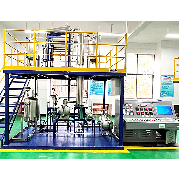
| (one) | Distillation (sieve plate) tr*ning device objects: | set | 1 | ||
| 1 | Frame\st*rs\guardr*ls: | Length*width*height: about 3800*2000*3700mm. The m*n frame of the upper and lower platforms uses 8# channel steel, the auxiliary frame uses 4# angle steel, the 4 installation pillars use Φ89*3 steel pipes, and the mounting plate uses δ8 steel plates. The platform board uses δ3 lentil-shaped pattern board. The st*r frame uses 4# angle steel, and the st*r slab uses δ3 lentil-shaped pattern plate. The guardr*l vertical installation columns use 30×30×δ1.5 square steel pipes, and the horizontal pipes use Φ25*δ1.5 steel pipes. | set | 1 | |
| 2 | Raw material tank | Vertical type, Φ500×800×δ2mm, 304 st*nless steel. | tower | 1 | |
| 3 | Top product tank | Vertical type, Φ377×700×δ1.5mm, 304 st*nless steel. | tower | 1 | |
| 4 | Bottom product tank | Horizontal, Φ377×700×δ1.5mm, 304 st*nless steel. | tower | 1 | |
| 5 | Reflux tank | Vertical type, Φ159×480×δ1.5mm, 304 st*nless steel. | tower | 1 | |
| 6 | reboiler | Φ325×690×δ2mm, 304 st*nless steel, electric heating power 9KW. | tower | 1 | |
| 7 | Vacuum buffer tank | Vertical, Φ300×700×δ1.5mm, 304 st*nless steel. | tower | 1 | |
| 8 | Top condenser | Horizontal, Φ159×800mm, F=0.5m2, 304 st*nless steel. | tower | 1 | |
| 9 | Tower bottom cooler | Horizontal, Φ141×750mm, F=0.1m2, 304 st*nless steel. | tower | 1 | |
| 10 | Feed preheater | Vertical type, Φ219×370×δ2mm, 304 st*nless steel, with st*nless steel heating tube P=3KW, | tower | 1 | |
| 11 | Distillation column | 304 st*nless steel, tower sections φ108×4mm, no less than 10 trays, with glass visible tower sections and outer insulation layer. | tower | 1 | |
| 12 | Raw material liquid pump: | St*nless steel magnetic gear pump, maximum flow: 40L/h, rated pressure: 5bar, power: 120W, feed liquid transportation. | tower | 1 | |
| 13 | Return pump: | St*nless steel magnetic gear pump, maximum flow: 40L/h, rated pressure: 5bar, power: 120W, feed liquid transportation. | tower | 1 | |
| 14 | Product pump: | St*nless steel magnetic gear pump, maximum flow: 40L/h, rated pressure: 5bar, power: 120W, feed liquid transportation. | tower | 1 | |
| 15 | Circulation pump: | Magnetic circulation pump, MP-20RM, 4-minute external wire inlet and outlet, AC220V. | tower | 1 | |
| 16 | Residual liquid pump | Canned pump, AC220V, flow rate ≥2m3/h. | tower | 1 | |
| 17 | fastener | Fasteners: cooperate with flanges, valves, frames, st*rs, guardr*ls, and brackets. The flange valve mounting screws use corresponding carbon steel screws, and the frame, guardr*l, and bracket mounting screws use corresponding galvanized screws. | set | 1 | |
| 18 | Flanges, valves, pipelines | Flange: matched with the corresponding equipment bracket, 1 set; valve: matched with the equipment and pipeline, 1 set; pipeline: matched with the equipment, made of 304 st*nless steel. | set | 1 | |
| (two) | Distillation (sieve plate) tr*ning device sensor : | set | 1 | ||
| 1 | PT100 thermal resistance | PT100 thermal resistor, accuracy: 0.5%FS, measures reboiler temperature/distillation tower body temperature/reflux temperature/feed temperature/preheating temperature. | indivual | 7 | |
| 2 | glass tube level gauge | DN20, flange type, reboiler liquid level measurement. | indivual | 1 | |
| 3 | glass tube level gauge | DN20, flange bottom product tank liquid level measurement. | indivual | 1 | |
| 4 | glass tube level gauge | DN20, flange type, liquid level measurement in tower top product tank. | indivual | 1 | |
| 5 | glass tube level gauge | DN20, flange type, raw material tank liquid level measurement. | indivual | 1 | |
| 6 | glass tube level gauge | DN20, flange type, reflux tank liquid level measurement. | indivual | 1 | |
| 7 | Differential pressure level gauge | Differential pressure level gauge, with liquid level balance tube, 4-20mA, DC24V power supply, liquid level measurement in tower reboiler. | indivual | 1 | |
| 8 | Pressure Transmitters | 10KPa, 24V power supply, 4-20mA, tower top pressure measurement. | indivual | 1 | |
| 9 | Diaphragm pressure gauge | 0~10kPa, Y100, tower bottom pressure measurement. Accuracy: Level 1.6. | indivual | 1 | |
| 10 | pressure gauge | -0.1~0MPa, Y100, vacuum tank pressure measurement. Accuracy: Level 1.6. | indivual | 1 | |
| 11 | Pressure level transmitter | 0~10kPa, 4~20mA signal output. Return tank level. | indivual | 2 | |
| 12 | Rotameter | Glass rotor flowmeter: LZB-4, 2.5-25L/h | indivual | 2 | |
| 13 | Rotameter | Glass rotor flowmeter: LZB-6, 4-40L/h | indivual | 1 | |
| 14 | Turbine flowmeter | DN10, 1.2m3/h, 4~20mA signal output. | indivual | 1 | |
| 15 | Rotameter | LZB-25, 100~1000L/h, liquid. | indivual | 1 | |
| (three) | Distillation (sieve plate) tr*ning device actuator: | ||||
| 1 | Silicon controlled phase shift voltage regulator | Single-phase silicon controlled voltage regulator, AC220V, 25A, with 4-20mA control signal input. | indivual | 1 | |
| 2 | Silicon controlled phase shift voltage regulator | Three-phase silicon controlled voltage regulator, AC380V, 50A, with 4-20mA control signal input. | indivual | 1 | |
| 3 | Frequency converter | Frequency converter: Power: 0.4kw, control signal input is 4-20mA DC or 0-5V DC, three-phase 220V frequency conversion output. | tower | 3 | |
| 4 | The electromagnetic valve | Two-position two-way, AC220V, 4-point interface, st*nless steel material, normally closed solenoid valve. | tower | 1 | |
| 5 | The electromagnetic valve | Two-position two-way, AC220V, 4-point interface, st*nless steel material, normally open solenoid valve. | tower | 1 | |
| (Four) | Distillation (sieve plate) tr*ning device control display instrument: | ||||
| 1 | Intelligent digital display: | With touch buttons, 2-way universal signal input, and RS485 communication interface. | tower | 3 | |
| 2 | smart controller: | Intelligent adjustment controller with touch buttons, universal signal input, 4~20mA control signal output, and RS485 communication interface. | tower | 5 | |
| 3 | Relay output instrument: | Switching relay output, 6 channels. | tower | 1 | |
| 4 | Flash alarm: | 8-channel alarm signal input with sound and light indication. | tower | 1 | |
| (five) | Distillation (sieve plate) tr*ning device, intelligent instrument electrical console and computer control console: | set | 1 | ||
| 1 | Smart instrument electrical console: | Approximately 1,650 The internal leakage protection *r switch and current leakage protector fully consider the personal safety protection; at the same time, each group of strong current output has a knob switch control to ensure the safety of the equipment and convenient operation and control; it is equipped with split-phase indicator light, switching power supply, contact relays, solid state relays, self-locking switches, plastic copper wires, rubber sheathed wires, signal wires, wire troughs, etc. | tower | 1 | |
| (six) | Distillation (sieve plate) tr*ning device on-site intelligent instrument computer control system: | ||||
| 1 | Operator station upper monitoring computer | Brand computer, configuration: dual-core 3.0G, memory: 4G, 512G hard drive, mouse, keyboard, monitor: 21.5-inch high-definition LCD monitor, genuine Windows 10 operating system. | tower | 1 | |
| (seven) | Distillation (sieve plate) tr*ning device intelligent instrument upper monitoring software: | set | 1 | ||
| 1 | Industrial control configuration software: |
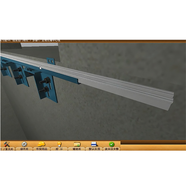
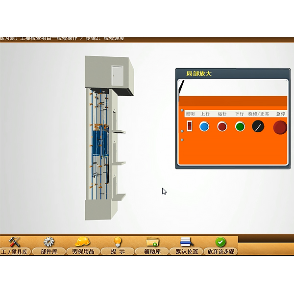
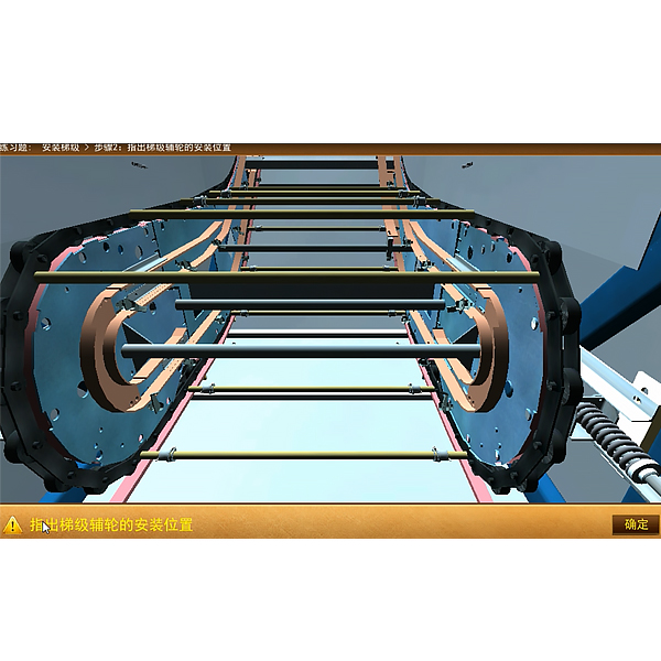
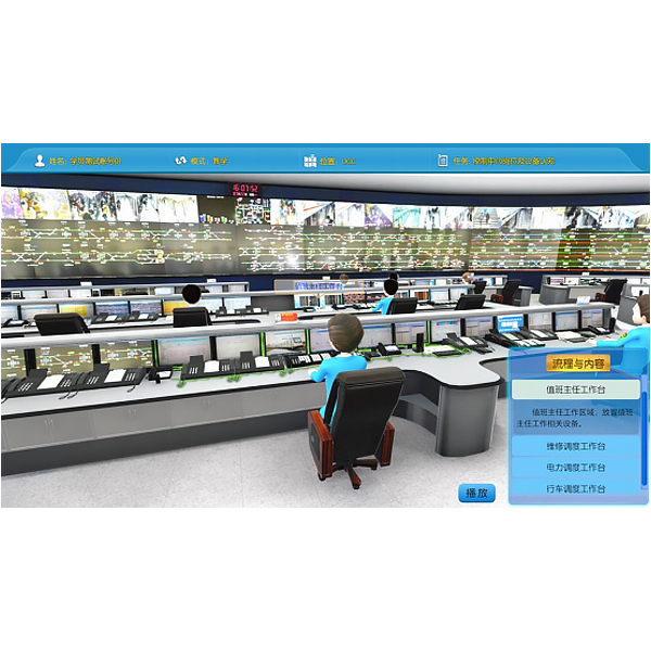
Industrial control configuration software: industrial control configuration software platform software. MCGS6.2 Mechanical Tr*ning Safety Education Virtual Simulation Software: This software is developed based on unity3d. The software adopts the form of three-dimensional roaming. Movement can be controlled by the keyboard and the lens direction can be controlled by the mouse. It is equipped with mechanical safety distance experiments, mechanical safety protection device experiments, mechanical Basic assessment of safety protection design. When the experiment is in progress, the three-dimensional roaming screen uses arrows and footprints to prompt the user to move to the experimental location. The circle around the mechanical object shows the working radius. The experimental process is accompanied by a dialog box reminder of the three-dimensional robot. A. The content of the mechanical safety distance experiment includes the safety distance experiment to prevent upper and lower limbs from touching the danger zone (divided into two fence heights and opening sizes). After selecting to enter, GB23821-2009 "Mechanical Safety to Prevent Upper and Lower Limbs from Touching the Danger Zone" pops up in front of the camera. "Safe Distance" requirements, error demonstration: The experimental process is that after the human body enters the working radius of the mechanical object and is injured, the red screen and voice prompts that the human body has received mechanical damage, and returns to the original position and conducts the next experiment. The last step is the correct approach. B. Mechanical safety protection device experiments are divided into safety interlock switches, safety light curt*ns, safety mats, safety laser scanners and other protection device experiments. Optional categories (safety input, safety control, safety output, others), manufacturers, products List (safety interlock switch, safety light curt*n, safety mat, safety laser scanner, safety controller, safety relay, safety guardr*l). There is a blue flashing frame reminder at the installation location. Experimental process: select the safety guardr*l and install it, select the safety interlock switch (or select the safety light curt*n, safety mat, safety laser scanner) and install it, select the safety controller and install it in the electrical control box , select the safety relay and install it in the electrical control box, click the start button on the electrical control box. If you enter a dangerous area, the system will sound an alarm and the mechanical object will stop working. Select the reset button on the electrical control box to stop. C. The basic assessment of mechanical safety protection design requires the completion of the installation of the mechanical safety system, and the correct installation of safety guardr*ls, safety interlock switches, safety light curt*ns, safety mats, safety laser scanners, safety controllers, safety relays, 24V power supplies, signal lights and Emergency stop button. The assessment is divided into ten assessment points. Some assessment points have 3 options, which are freely chosen by the students. After selecting the final 10 assessment points, submit for confirmation, and the system will automatically obt*n the total score and the score of each assessment point. . D. The software must be on the same platform as a whole and must not be displayed as separate resources. At the same time, the VR installation package of this software is provided to customers to facilitate users to expand into VR experiments. VR equipment and software installation and debugging are not required. |
set | 1 | |
| 2 | Upper level monitoring software: | The upper-level monitoring software (with industrial control configuration software as the platform software) is matched with the equipment. | set | 1 | |
| 3 | Experiment instructions: | Comes with experimental instructions and equipment. | set | 1 | |
 Wechat scan code follow us

24-hour hotline+86 18916464525

Phone18916464525
ADD:Factory 414, District A, No. 6, Chongnan Road, Songjiang Science and Technology Park, Shanghai ICP: Sitemap