dyxnydc-03 Power Battery Pack experimental device
Release time:2024-05-24 23:30viewed:times
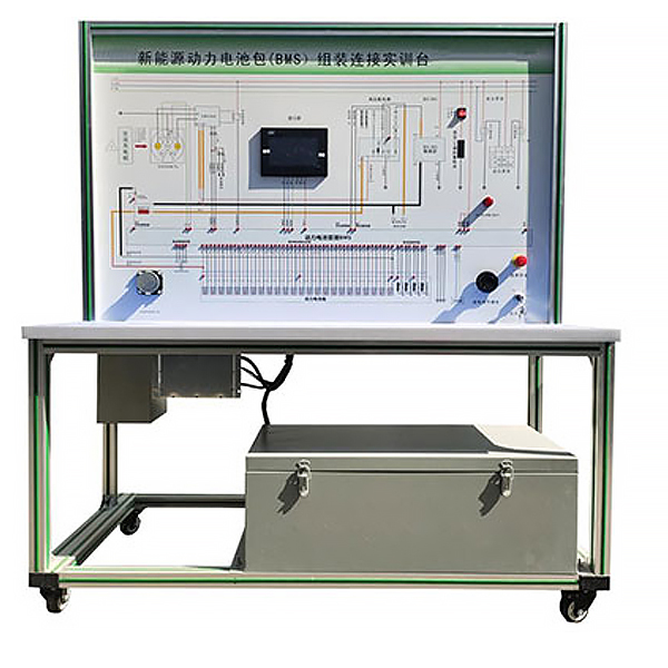
1. Product introduction:
The m*nstream new energy lithium iron phosphate power battery pack is selected. The single battery is 3.2V 10AH, with a total of 16 strings. The integrated BMS battery management system has a passive balancing function; it truly presents the core components of the lithium iron phosphate power battery pack. The connection control relationship between components, installation location and operating parameters, as well as safety precautions for high-voltage systems; by comparing the circuit schematic diagram, students assemble the connections themselves, cultivating students' hands-on ability in battery assembly and connection, which is suitable for teaching new energy courses in colleges and universities and rep*r tr*ning equipment.
2. Functional features
1. Students can disassemble and assemble the battery pack and BMS management system manually.
2. The m*n components are installed on the platform. After students disassemble and assemble the battery pack and BMS management system, they can actually operate the battery pack and BMS management system.
3. The BMS battery management system is installed on the panel, with clearly marked logical control relationships such as voltage acquisition lines, temperature acquisition lines, relay control lines, and Hall current sensor acquisition lines.
4. The BMS battery management system has a passive balancing function, switch control protection (cell disconnection, short circuit, overvoltage, undervoltage, overcurrent, overtemperature), and estimates SOC (state of charge), etc. (Supported with BMS host computer detection and calibration software that can operate normally) 5. The power battery pack display (7 inches) is installed on the panel. You can observe various parameters of the charging and discharging process and master the control logic and m*n components of
the charging and discharging process of the power battery pack. Parameter change rules.
6. The tr*ning platform is equipped with a discharge module to simulate the vehicle energy consumption process, and the discharge current size can be selected.
7. The power battery pack is equipped with a mechanical m*ntenance switch, and the high-voltage electrical connectors are all national standard products with reliable performance.
8. The tr*ning platform is equipped with a 12V power ground mechanical switch, which can disconnect the 12V ground at any time and cut off the power supply of the entire system.
9. The UV flatbed printing panel completely displays the working principle diagram of the power battery pack, BMS, charging and discharging. There are detection terminals installed on the panel, which can directly detect the electrical signals of the system circuit components on the panel, such as resistance, voltage, current and frequency. Signal etc.
10. The tr*ning platform consists of a mobile platform (principle panel with detection terminals). The platform is placed horizontally and the m*n components are installed. 4 casters are installed at the bottom of the tr*ning platform, which allows flexible movement. At the same time, the casters have self-locking devices and can be fixed in position. .
11. The equipment frame is constructed of two integrated all-aluminum alloy profiles, 40mm×40mm and 40mm×80mm, which are oil-resistant, corrosion-resistant and easy to clean. The countertop is 40CM wide and paved with 32mm thick colored high-density composite boards, which is durable and rust-free. , with 4 swivel casters with self-locking devices for easy movement.
12. Equipped with teaching materials such as practical tr*ning guides, which fully describe the working principles, practical tr*ning projects, fault settings and analysis and other key points.
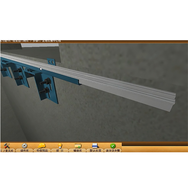
13. Mechanical assembly and fitter assembly virtual simulation software: This software is developed based on unity3d, with optional 6-level image quality. It is equipped with the design and virtual disassembly and assembly of reducers and shafting structures, the design and simulation of common mechanical mechanisms , and a mechanism resource library. For a typical mechanical mechanism (virtual disassembly and assembly of a gasoline engine), the software is a whole software and cannot be individual resources.
A. Reducer design and virtual disassembly interface can choose worm gear bevel gear reducer, two-stage expanded cylindrical gear reducer, bevel cylindrical gear reducer, coaxial cylindrical gear reducer, bevel gear reducer, and one-stage cylindrical gear reducer. Gear reducer.
Worm bevel gear reducer: After entering the software, the assembly content is automatically played. Each step in the video has a text description
. Secondary expandable cylindrical gear reducer: After entering the software, the content is played in the form of a video. The video content should include: Part name ( Scan the QR code to see the names of parts), disassembly and assembly demonstration (including disassembly and assembly), virtual disassembly (including overall, low-speed shaft, medium-speed shaft, high-speed shaft, box cover, box seat)
conical cylindrical gear reducer, Coaxial cylindrical gear reducer, bevel gear reducer, first-level cylindrical gear reducer: click to enter and automatically jump to the edrawings interface. The models are all three-dimensional models . By clicking on the parts, the names of the parts are displayed, and the 360° view is av*lable Rotate, enlarge, reduce, translate, and at the same time, the entire reducer can be disassembled and assembled through the moving parts function. At the same time, you can select the home button to return to the original state of the reducer. The bevel gear reducer and first-stage cylindrical gear reducer have added the function of inserting a cross section, and the cross section can be freely dragged to observe the internal structure of the reducer.
B. Shaft structure design and virtual disassembly and assembly interface optional parts recognition, disassembly and assembly demonstration, and actual operation.
1. Parts recognition: three-dimensional model and part name including helical gear, non-hole end cover, coupling, coupling key, shaft, gear key, hole end cover, shaft sleeve, deep groove ball bearing, any All parts can be rotated 360°
2. Disassembly and assembly demonstration: There are 2 built-in cases. When you move the mouse to the position of a cert*n part (except the base and bearing seat), the part will automatically enlarge and the name of the part will be displayed. It is equipped with disassembly and Assembly button, the function is to automatically complete the disassembly and assembly of the shaft system structure by the software. All three-dimensional scenes can be rotated, enlarged, reduced and translated 360° in all directions.
3. Practical operation: The three-dimensional parts are neatly placed on the table. Students manually select the corresponding parts and move them to the shaft system structure. The parts can be installed only when they are placed in the correct order and in the correct position. There is a restart button to facilitate students to restart. Conduct virtual experiments. When you move the mouse to a cert*n part position (except the base and bearing seat), the part will automatically enlarge and the part name will be displayed.
C. Common mechanical mechanism design and simulation, optional hinge four-bar mechanism design and analysis, I\II type crank rocker mechanism design and analysis, offset crank slider mechanism design and analysis, crank swing guide rod mechanism design and analysis, hinge Four-bar mechanism with integrated trajectory, eccentric linear-acting roller push rod cam , and centering linear-acting flat-bottomed push rod cam .
1. Each mechanism should be able to input corresponding parameters, and the software can automatically calculate the parameters, and can perform motion simulation and automatically draw curves.
D. The mechanism resource library includes 11 types of planar link mechanisms, 5 types of cam mechanisms, 6 types of gear mechanisms, 8 types of transmission mechanisms, 11 types of tightening mechanisms, 6 types of gear tr*n mechanisms, and 8 types of other mechanisms (mechanical equipment simulation)
E , Virtual disassembly and assembly of gasoline engines, optional crankcase assembly and disassembly demonstration, crankcase virtual assembly, valve tr*n assembly and disassembly demonstration, valve tr*n virtual assembly
1. Both the crankcase assembly and disassembly demonstration and the gas distribution system assembly and disassembly demonstration are equipped with disassembly buttons, assembly buttons, restart, and disassembly observation buttons. When the mouse is moved to a cert*n part position, the part will automatically enlarge and the part name will be displayed. , the function is to automatically complete the disassembly and assembly of the shaft system structure by the software. When the decomposition observation button is used, the 3D model of the crankcase or gas distribution system automatically displays an exploded view, which can be rotated, enlarged, reduced, and translated 360°.
2. The 3D parts of the crankcase virtual assembly and the gas distribution system virtual assembly are neatly arranged When placed on the desktop, students manually select the corresponding parts and move them to the mechanism. The parts can be installed only when they are placed in the correct order and in the correct position. There is a restart button to facilitate students to re-perform the virtual experiment. When you move the mouse to cert*n part locations, the part names are automatically displayed.
3. Technical specifications
1. Overall dimensions (mm): 1500×700×1700mm (length*width*height)
2. Input power supply: AC220V±10% 50Hz
3. Working power supply: DC12V
4. Power battery type: Environmentally friendly iron phosphate Lithium power battery (single cell 3.2V 10AH)
Number of power battery strings: 16
Working temperature: -20°~60°
5. BMS lithium battery management machine: with CAN communication
6. Power battery pack display: 7-inch touch screen
7. High voltage and high current relay: coil voltage: 12VDC, maximum rated operating voltage: 1000VDC, rated current: 400A.
4. Practical tr*ning project
1. Students assemble battery packs and BMS by hand, and understand the control principles of new energy power battery packs (BMS).
2. Students assemble the battery pack and BMS by hand, and understand the functions of the m*n components of the new energy power battery pack (BMS).
3. Through the connection and running actual measurement, familiarize yourself with the logical control relationship of the new energy power battery pack (BMS) in various states, and the practical tr*ning experiments on the changing rules of parameters such as current, voltage, battery voltage difference, and battery temperature.
4. Through actual connection measurements, become familiar with how BMS collects the voltage difference of the power battery pack and controls the charging and discharging process.
5. Through actual connection measurements, become familiar with how BMS collects the temperature difference of the power battery pack and controls the charging and discharging process.
5. Basic configuration:
lithium iron phosphate power battery pack, experimental connection wires, BMS lithium battery management machine, 7-inch power battery pack touch display, vehicle charger , national standard charging socket, national standard charging gun, emergency power-off switch, Hall current Sensor, DC contactor (including charging relay, total positive relay, total negative relay, precharge relay), DC-DC converter, auxiliary battery (12V45AH), discharge control relay and discharge load, precharge resistor, integrated all-aluminum Mobile stand made of alloy profiles (1500×700×1700mm, with self-locking casters, with a principle panel for installing detection terminals, panel 1448×940mm), and equipment operating instructions.


 Wechat scan code follow us
