Shanghai Daiyu Education Equipment Manufacturing Co., Ltd.
Language:


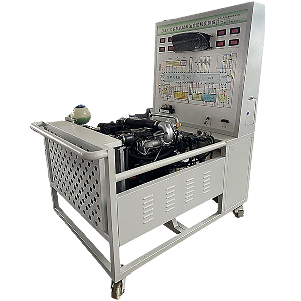


| serial number | name | Specifications and models | unit | quantity |
| 1 | Test control panel |
Equipped with various detection terminals and color circuit diagram (950*900*4mm aluminum-plastic plate) |
set | 1 |
| 2 | instrument cluster | set | 1 | |
| 3 | Engine control computer (ECU) | tower | 1 | |
| 4 | Diagnostic seat | indivual | 1 | |
| 5 | Ignition Switch | indivual | 1 | |
| 6 | Electronically controlled high-voltage common r*l diesel engine assembly | set | 1 | |
| 7 | Fuel tank | 10L | indivual | 1 |
| 8 | Throttle control | set | 1 | |
| 9 | Intake and exhaust pipes | set | 1 | |
| 10 | Water tank (including protective cover) | set | 1 | |
| 11 | cooling electronic fan | indivual | 2 | |
| 12 | Air filter and intake pipe | set | 1 | |
| 13 | battery | tower | ||
| 14 | relay | Including: m*n relay, starting relay, cooling fan relay, preheating relay, etc. | set | 1 |
| 15 | Fuse box | indivual | 1 | |
| 16 | m*n power switch | 50A | indivual | 1 |
| 17 | Mobile stand (with self-locking casters) | 1500×1000×1700mm (length×width×height) | tower | 1 |
| 18 | Fault simulation and troubleshooting device | set | 1 | |
| 19 | Equipment Teacher's Manual | set | 1 | |
| 20 | Equipment certificate, warranty card | set | 1 |
 Wechat scan code follow us

24-hour hotline+86 18916464525

Phone18916464525
ADD:Factory 414, District A, No. 6, Chongnan Road, Songjiang Science and Technology Park, Shanghai ICP: Sitemap