Shanghai Daiyu Education Equipment Manufacturing Co., Ltd.
Language:


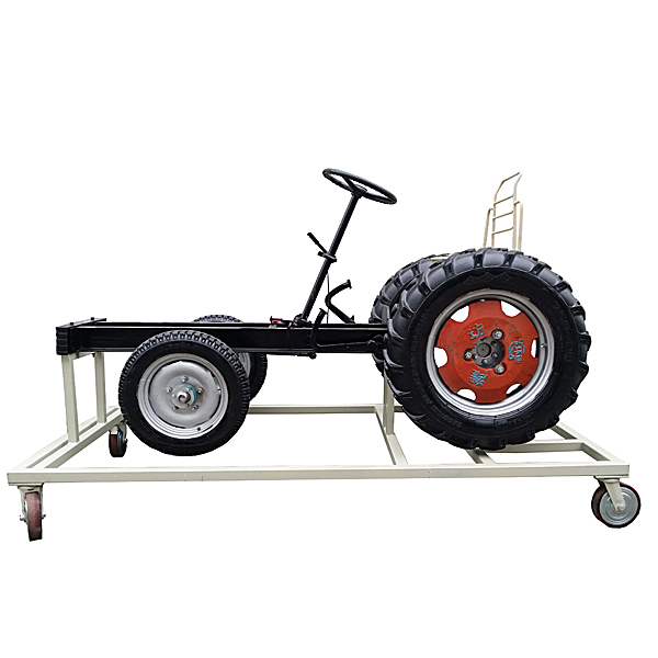


| serial number | name | Specifications and models | unit | quantity |
| 1 | Front axle assembly | set | 1 | |
| 2 | Rear axle assembly | set | 1 | |
| 3 | brake pedal | set | 1 | |
| 4 | Brake master cylinder and brake cylinder | set | 1 | |
| 5 | Braking system accessories | set | 1 | |
| 6 | Mobile stand (with self-locking casters) | 2000×1400×1200mm (length×width×height) | tower | 1 |
| 7 | seat | open | 1 | |
| 8 | three phase motor | 2.2KW380V | tower | 1 |
 Wechat scan code follow us

24-hour hotline+86 18916464525

Phone18916464525
ADD:Factory 414, District A, No. 6, Chongnan Road, Songjiang Science and Technology Park, Shanghai ICP: Sitemap