Shanghai Daiyu Education Equipment Manufacturing Co., Ltd.
Language:

PRODUCT

PRODUCT CENTER

DYYY-03Y Industrial Smart Smart Hydraulic Comprehensive Training Device

Release time:2024-05-18 16:00viewed:times
  • DYYY-03Y Industrial Smart Smart Hydraulic Comprehensive Training Device
The ZRYY-03Y intelligent hydraulic comprehensive experimental device has a development test analysis system, intelligent data collection hydraulic experimental device, and intelligent hydraulic comprehensive experimental device through flow, pressure, power, rotational speed, displacement, time, temperature, computer human-machine screen --Computer intelligent data collection, analysis, processing, --automatic production of reports, curves and a series of intelligent actions, complete various conventional dynamic and static tests of hydraulic circuits, motors, various valves and pumps and other experiments. Through the intelligent data collection hydraulic test bench intelligent hydraulic comprehensive experimental device experiment, the performance testing, intelligent control, remote control and communication technology of the hydraulic system and computer can be mastered and improved.
1. Technical parameters:
1) Input power supply voltage: three-wire and five-wire AC380V±10% 50HZ;
2) DC voltage of modules and components: DC24V, 4.5A, with automatic short-circuit protection function;
3) Control voltage: safety control voltage - DC24V ;
4) Usage environment: temperature -10℃~+40℃, relative humidity <85% (25℃), altitude <4000m (dust-proof and moisture-proof);
5) Product size: length × width × height = 2450mm*700mm*1850mm;
6 ) Total power: <=5KW;
7) Rated pressure: <=7Mpa;
8) Net weight: about 295kg;
9) Hydraulic pump unit components: (Double pump unit)
System rated working pressure: 6Mpa. (Maximum up to 7Mpa)
(1) Motor -pump device (2 units)
A. Fixed vane pump: nominal discharge 6.3ML/r, volumetric efficiency 80%;  
fixed vane pump drive motor: three-phase AC voltage, power 1.5 KW, Rotating speed 1450r/min;
equipped with pilot relief valve.
B. Variable vane pump: low-pressure variable vane pump, nominal displacement 6.67ML/r, pressure adjustment range 4~7Mpa;
variable vane pump motor: three-phase AC voltage, power 1.5KW, speed 1450r/min;
(2) Fuel tank: Nominal volume 100L; equipped with liquid level and oil temperature indicators, oil suction and oil return filters, safety valves, etc.;
(3) High-quality hydraulic oil: PetroChina 32# anti-wear hydraulic oil
(4) Air cooler: pressure 0 -1.6Mpa; flow rate: 40L;
(5) Virtual multimeter parameters:
AC voltage range points: 10, 50, 250, 1000
DC voltage range points: 0.25, 1, 2.5, 10, 50, 250, 1000
ohms Gears: x1, x10, 100, 1000, 1K, x10K, x100K
Ammeter gears: 50μa, 0.5, 5 ,
50, 500 BATT: 1.2-3.6V, RL=12Ω
BUZZ: R×3
infrared emission detection Function: Vertical angle ±15°, distance 1-30cm
triode measuring hole
2. M*n features:
1. Experimental bench: Intelligent hydraulic comprehensive experimental bench device with all-steel frame, the m*n material is 2.0mm thick steel plate, the pump unit is closed and hidden The experimental platform is designed with drawers, storage cabinets and placement brackets. The experimental platform is designed with an oil return tray; it is equipped with universal wheels with a self-locking structure to facilitate the movement and positioning of the equipment.
2. Connection method and sealing material: The hydraulic connection method adopts a locking quick-change joint. The seals are all imported high-sealing products, and there will be no oil leakage during use.
3. Electrical components: power supply, electrical switches, relay groups, AC contactors, etc. It is also equipped with a relay group, solenoid valve electronic control unit, electrical button module and time relay module. The electrical access ports are all attached to the electrical control panel of the experimental bench, and the experimental wires can be used for convenient plug-in connection during the experiment;
4. Safety performance: The intelligent hydraulic comprehensive test bench device is equipped with electrical grounding, leakage protection (automatic power-off when the ground leakage current exceeds 30mA), phase loss protection, and DC overload protection. The control circuits are all 24V DC safety voltage, and the electrical wires are safety high-insulation experimental wires.
5. Software: The intelligent data collection hydraulic test bench and the intelligent hydraulic comprehensive experimental device are equipped with 3 sets of software, namely: 1 set of data acquisition system software, 1 set of hydraulic simulation teaching software, and 1 set of configuration hydraulic circuit communication control software. ;
6. Multiple control methods: plc control, relay control, manual control, software control, network control, touch screen control and other control methods.
3. Experimental projects:
1. Experimental fluid to understand the working principle of standard series hydraulic components
2. Hydraulic component performance test experiment;
(1) Hydraulic pump performance test experiment;
a. No-load performance test of hydraulic pump;
b. Hydraulic pump mechanical Characteristic testing of efficiency, volumetric efficiency, and total efficiency.
(2) Static characteristics experiment of the relief valve;
a. Pressure regulating range measurement; b. Pressure swing measurement; c. Pressure offset measurement;
d. Pressure loss measurement; e. Unloading loss measurement; f. Internal leakage Measurement; g. Measurement of opening and closing characteristics.
(3) Dynamic characteristics experiment of the relief valve;
a. Testing of the pressure step response characteristic curve of the relief valve;
b. Dynamic parameters of the relief valve (steady-state pressure, test flow, unloading pressure, pressure amplitude, pressure overshoot, pressure peak, pressure rise time, unloading time (loading time, transition time, etc.) physical meaning and calculation method.
(4) Throttle valve characteristic test experiment;
a. Test of variable load speed-load characteristics and power characteristics;
b. Test of power characteristics under constant load conditions;
c. Inlet throttle speed regulation, oil return section Flow speed regulation and bypass throttling speed regulation.
(5) Characteristic test experiment of speed regulating valve;
a. Test of variable load speed-load characteristics and power characteristics;
b. Test of power characteristics under constant load conditions;
c. Characteristic test of speed regulation of oil inlet speed valve .
(6) Static performance experiment of pressure reducing valve;
a. Test of static characteristic parameters of pressure reducing valve (pressure regulating range, pressure swing, pressure offset, internal leakage, etc.);
b. Inlet-outlet characteristics of pressure reducing valve Curve test;
c. Test of pressure reducing valve outlet pressure-flow characteristic curve.
(7) Dynamic characteristic performance experiment of the pressure reducing valve;
a. Test of the pressure step response characteristic curve of the pressure reducing valve;
b. Various parameters of the dynamic characteristics of the pressure reducing valve (steady state pressure, test flow, unloading pressure, pressure Amplitude, pressure overshoot, pressure peak, pressure rise time, pressure relief time, transition time, etc.) physical meaning and calculation method.
(8), Hydraulic cylinder performance experiment;
3. Basic hydraulic circuit experiment
(1), Pressure control circuit experiment;
A. Pressure limiting circuit:
a. Pressure setting circuit;     
b. Relief valve single-stage remote pressure regulating circuit;
c. Multi-stage relief valve pressure regulating circuit;
d. The relief valve limits the low-pressure circuit (balance circuit).
B. Transformer circuit:
a. Primary pressure reduction circuit;      
b. Secondary pressure circuit; multi-channel pressure reduction circuit.
C. Unloading circuit:
a. Unloading circuit of reversing valve; 
b. Unloading circuit of electromagnetic reversing valve;
c. Unloading circuit of relief valve.
D. Pressure stabilizing circuit:
a. Hydraulic control check valve pressure m*nt*ning circuit.
E. Pressure relief circuit:
a. Throttle valve pressure relief circuit;     
b. Relief valve pressure relief circuit;      
c. Sequence valve pressure relief circuit.
F. Pressure reducing circuit
a. Pressure reducing circuit of pressure reducing valve
(2), speed control circuit experiment;
A. Speed ​​regulating circuit:
a. Oil inlet throttling speed regulating circuit (constant pressure throttling speed regulating circuit, variable pressure regulating circuit) flow speed control circuit);
b. Oil return throttle speed control circuit;                
c. Speed ​​switch for short circuit of flow valve;
d. Speed ​​control valve control speed control circuit I (oil inlet: speed control valve constant pressure throttling control speed, speed control valve variable pressure throttling speed control);
e. Speed ​​control valve controls speed control circuit II (oil return: bypass speed control);                 
f. Deceleration circuit of solenoid valve and speed control valve;
g. Throttle valve Secondary feed circuit in series/parallel connection;       
h. Secondary feed circuit in series/parallel connection of speed regulating valves;
i. Speed ​​switching circuit in series connection of speed regulating valves;          
j. Speed ​​switching circuit in parallel connection of speed regulating valves;                  
k , Differential circuit controlled by two-position three-way
l. Differential circuit controlled by three-position four-way
B. Synchronous loop:
a. Synchronous loop controlled by throttle valve;              
b. Synchronous loop controlled by speed regulating valve;
c. Double cylinder Synchronous loop;                      
(3) Direction control loop experiment;
A. Reversing loop:
a. Reversing valve controlled reversing loop;                
c. Sequential action loop of sequence valve;              
d. Sequential action loop controlled by electric travel switch;    
e. The sequential action circuit controlled by the pressure relay;
f. The sequential action circuit controlled by the one-way valve.
B. Locking circuit:
a. Use a reversing valve to lock the circuit;                  
b. Locking circuit of hydraulic control one-way valve;
c. Locking circuit                    
of one-way valve; d. Locking circuit of "O" type or "H" type functional reversing valve. 
C. Sequential circuit:
a. Using sequence valve Sequential action circuit;          
b. Sequential action circuit using electric travel switch;
c. Sequential action circuit using pressure relay.
D. Balance circuit:
a. Balance circuit using sequence valve;              
b. Balance circuit using hydraulic control one-way valve;
c. Balance circuit using one-way speed regulating valve;          
d. Balance circuit using one-way throttle valve.
E. Buffer circuit:
a. Balance circuit using relief valve;              
b. Buffer circuit using speed regulating valve;
c. Buffer circuit using throttle valve.
(4) Other comprehensive assembly and scalable loop experiments.
4. Intelligent data acquisition system experiment: real-time experimental data collection, analysis, processing, real-time display, automatic generation of experimental curves, printing and other functions of pressure, flow, power, rotation speed, temperature, displacement and other data.
5. Programmable controller (PLC) electrical control experiment, electromechanical and hydraulic integration control experiment.
(1), PLC instruction programming, ladder diagram programming learning;
(2), PLC programming software learning and use;
(3), PLC and computer communication, online debugging, monitoring;
(4) PLC hydraulic transmission Application in control and optimization of control schemes.
4. Software configuration:
1. Hydraulic simulation control system:
Hydraulic simulation control software is a hydraulic simulation control system developed based on KingView, including 20 typical hydraulic circuit controls and demonstrations. It vividly displays the flow direction of pressure oil, the working status of the internal valve cores of various hydraulic valves, the working process of the oil cylinder, and the working principle of the gear pump in the simulation circuit one by one. More than 10 of them can be directly connected to the hardware to control the work of the hardware system and monitor the entire working process to achieve the effect of synchronous work of software and hardware. The hydraulic simulation control simulation system includes the following (specific circuit differences are subject to the latest standards):
2. Hydraulic control system included in the hydraulic simulation software:
1) Pressure regulation circuit - two-stage pressure regulation circuit;
2) Two-position two-way Solenoid reversing valve unloading circuit;
3) Two-position four-way solenoid reversing valve reversing circuit;
4) Three-position four-way solenoid reversing valve reversing circuit;
5) Manual reversing valve reversing circuit;
6) Oil inlet Throttle and speed regulating circuit;
7) Return oil throttling and speed regulating circuit;
8) Bypass oil throttling and speed regulating circuit;
9) Stroke switch controls the reversing circuit of two three-position four-way electromagnetic reversing valves;
10) Sequence valve control Sequential action circuit (travel switch);
11) Speed ​​switching circuit: fast-slow speed switching circuit;
12) Speed ​​switching circuit: fast-slow-working speed switching (throttle valve series connection)
13) Speed ​​switching circuit Circuit: fast-slow-working speed switching (throttle valve in parallel);
14) Locking circuit;
15) Throttle valve control synchronous circuit;
16) Stroke control differential differential circuit;
17) Pressure m*nt*ning and releasing of pressure relay Loading circuit;
18) Hydraulic control check valve pressure m*nt*ning circuit;
19) Multi-stage pressure regulating circuit;
20) Sequential action circuit controlled by pressure relay.
(1) Hydraulic simulation software; (optional computer required)
1. Provides a large library of hydraulic and electrical standard components, and can set the technical parameters of related components in the circuit. Be able to learn hydraulic knowledge and design, test and simulate circuits;
2. Be able to design and draw circuit diagrams that comply with industrial standards, including: hydraulic circuit diagrams, electrical control circuit diagrams, and hydraulic-electric control circuits;
3. The software can identify circuits Whether the design is correct and prompts will be given;
4. Provide free upgrades.
5. Hydraulic and pneumatic transmission design and control virtual simulation software.
This software is developed based on unity3d. The software adopts the form of three-dimensional roaming. Movement can be controlled by the keyboard and the lens direction can be controlled by the mouse. The interface has home page, help, full screen, component recognition, and circuit construction. , key component testing, typical system testing interface.
5.1 Component identification adopts the form of automatic playback, which introduces the m*lbox, liquid level gauge, oil pump unit on the equipment (the pop-up hydraulic symbols, principles and introduction are introduced here, click OK to enter the next introduction), valve frame, pressure gauge, Sensors, etc.
5.2 Component disassembly and assembly are divided into learning mode and assessment mode. There are built-in electromagnetic reversing valves, plate relief valves, plunger pumps, filter valves, and electro-hydraulic servo valves. The disassembly sequence is prompted and highlighted in the learning mode. It is disassembled in the assessment mode. There is no prompt for installation. If the disassembly and assembly sequence is wrong, the next step of disassembly and assembly will not be possible. The toolbar is equipped with draggable seals, pumps, valves, oil filters, hex wrenches, pipe wrenches, adjustable wrenches, dead wrenches, and M5 screws.
5.3 The hydraulic components are equipped with one-way valve (hydraulic control, poppet valve core, ball valve core), m*n structure of the reversing valve (O type, Y type, H type), hydraulic cylinder (assembled plunger, double-acting single outlet rod, The construction of double-acting double-output rod, single-acting double-output rod, single-acting single-output rod), etc., each construction experiment adopts a graphical method, and is constructed by dragging the set graphics. There are Confusing graphics.
5.4 Hydraulic selection is based on the hydraulic schematic diagram, and then selects the nominal displacement of the pump (12 items, including 11 confusing items) and pressure level (5 items, including 4 confusing items), and the selection of the electromagnetic relief valve (3 items specifications, 3 image pressure levels, and 3 flow levels, all of which have confusing items), oil filter selection (multiple choices include confusing items), servo valve selection (multiple choices include confusing items), and the system will automatically Prompt for the correct answer. After selecting, drag the corresponding tool to the highlighted area according to the prompt.
5.5 Loop inspection is done by selecting the correct accessories, including the selection of sealing rings, checking valve switches, etc. Then the next step is to turn on the machine. Turn on the machine according to the prompts. After turning on the machine, enter the monitoring interface. Turn on the equipment one by one according to the prompts. The prompts are in the form of text and button highlighting.
5.6 Hydraulic cylinder pressure test. Enter the experiment through the test button on the background interface, which is gradually divided into Start friction test, start friction force, parameter settings, start test, draw curve, stop test.
5.7 Typical system tests are divided into trial operation, stage response test, and frequency response test. The above tests are all conducted through the background monitoring interface.
5.8 The software must be able to rotate, zoom in and out in all directions to view its det*ls. And the same platform as a whole cannot be displayed as separate resources.
(2) Mitsubishi programming software: (optional computer required)
(3) Can carry out basic knowledge learning and application such as PLC instruction programming, ladder diagram programming;
1. Can carry out the design, testing and simulation of PLC control loops;
2. Provide free Upgrade
3. Data acquisition software:
a) Introduction to data acquisition system functions.
This data acquisition system uses AD cards as data acquisition boards; the configured sensors are all high-precision sensors with an accuracy level of 0.5 or above (pressure sensing transmission can be configured sensor, turbine flow sensor, temperature transmitter, displacement sensor transmitter, power transmitter, torque speed sensing transmitter, etc.), each sensing transmitter has a standard signal output, and the external connecting cables of the sensor are Use special cables with good shielding effects to ensure the accuracy of data collection. The data acquisition software collects data from the output signals of this series of sensors, draws relevant curves in real time, generates real-time data reports, draws dynamic curves on any XY axis, and has curve printing functions, data report saving and printing functions, and parameters of each sensor. Setting functions and so on. Realize computer intelligent data collection, analysis, processing, digital display, automatic curve generation and real-time monitoring functions, in line with the future development trend of hydraulic control.
Industrial intelligent hydraulic comprehensive test bench configuration list

serial number Name Specifications and models quantity Remark
Experimental console
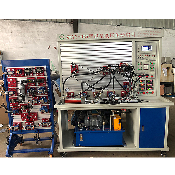
Experimental bench Welded steel structure 1 set Chinese teachings
Auxiliary experimental bench Steel structure and aluminum profiles overlapped 1 set Chinese teachings
Universal wheel With self-locking function; roller bearing 4 Install the bottom of the experimental bench
foot pads adjustable fixed 4 Install the bottom of the experimental bench
Hydraulic power station
Special pump station control system
(1 set)
Open with leakage protection 1 CHNT
AC contactor   2 CHNT
220V relay 2 Omron
emergency button 1 Chinese teachings
Button (red, green) 2 each Chinese teachings
10  indicator light 2 Chinese teachings
11  emergency button 1 each Chinese teachings
12P Fixed vane pump + drive motor Rated displacement: 6.3ml/r
Rated pressure: 6.3MPa
Rated power: 1.5kw
Rated voltage: AC380V
1 set Chinese teachings
13  Variable vane pump + drive motor Rated displacement: 6.67ml/r
Rated pressure: 7MPa
Rated power: 1.5kw
Rated voltage: AC380V
1 set Chinese teachings
14  Accumulator NXQ-0.6L 1 set K*hong Hydraulic
15  tank Rated volume 100L 1 Chinese teachings
16  *r filter HS-1163 1 Densheng Hydraulic
17  oil suction filter MF-04 1 Densheng Hydraulic
18  Oil temperature and oil level gauge LS-3 1 Densheng Hydraulic
19  *r cooler AW0607-CA1∮220V 1 Hengchang
20  oil pipe 1.5 m 2 pieces Chinese teachings
Hydraulic accessories
twenty one  Double acting hydraulic cylinder assembly Component model: HOB-50*200-LB
Maximum stroke: 200mm Bore size 50
2  
twenty two  Throttle valve stop valve assembly Component model: DV12-1-10B/2 2 Huade Hydraulic
twenty three  One-way valve assembly Component model: S10A02B/ 2 Huade Hydraulic
twenty four  Hydraulic control check valve assembly Component model: SV10PB1-30B/
Component model: FQ-SV10-3F
2 Huade Hydraulic
25  Relief valve (direct-acting) components Component model: DBDH6P10B/100
Component model: FQ-DH6P-2F
2 Huade Hydraulic
26  Relief valve (pilot type) components Component model: DB10-1-30B/100U
Component model: FQ-DB10-3F
1 Huade Hydraulic
27  Sequence valve components Component model: DZ10-1-30B/210Y
Component model: FQ-DZ6-3F
2 Huade Hydraulic
28  One-way speed regulating valve assembly Component model: 2FRM5-31B/15QB
Component model: FQ-2FRM5-2F
1 Huade Hydraulic
29  Pressure reducing valve assembly Component model: DR10-1-30B/100Y
Component model: FQ- DR10-2F
1 Huade Hydraulic
30  Two-position three-way electromagnetic reversing valve assembly Component model: 3WE6A61B/CG24N9Z5L
Component model: FQ-3WE6A-3F
1 Huade Hydraulic
31  Two-position four-way solenoid valve assembly Component model: 4WE6C61B/CG24N9Z5L
Component model: FQ-4WE6C-3F
2 Huade Hydraulic
32  Three-position four-way solenoid directional valve (O) components Component model: 4WE6E61B/CG24N9Z5L
Component model: FQ-4WE6E-3F
2 Huade Hydraulic
33  Three-position four-way solenoid directional valve (M) components Component model: 4WE6G61B/CG24N9Z5L
Component model: FQ-4WE6G-3F
1 Huade Hydraulic
34  Two-position four-way manual reversing valve assembly Component model: 4WMM6E50B/
Component model: FQ-4WMM6E-3F
1 Huade Hydraulic
35  Pressure relay components Component model: HED80A1X/100Z14KW
Component model: FQ-HED8-1M
2 Huade Hydraulic
36  Four-way components Component model: FQ-4T-3F 4 Chinese teachings
37  Dosing pump oil inlet assembly   1 Chinese teachings
38  Dosing pump pressure regulating component DBDH10P10B/100 1 Huade Hydraulic
39  Variable pump oil inlet assembly   1 Chinese teachings
40  Variable pump pressure regulating component DBDH10P10B/100 1 Huade Hydraulic
41  System oil return components   1 Chinese teachings
42  Glycerin pressure gauge components Component model: FQ-10MP a-1F-1M 4 relda
43  High pressure oil hose assembly Component model 16-1-25.6MP a-2M-0.7 10 sticks Chinese teachings
44  High pressure oil hose assembly Component model 16-1-25.6MP a-2M-1.0 10 sticks Chinese teachings
45  High pressure oil hose assembly Component model 16-1-25.6MP a-2M-1.5 5 sticks Chinese teachings
46  Hydraulic valve transition base plate A special base plate for hydraulic valves is installed on the valve 20 yuan Chinese teachings
47  Quick change connector male connector Open and close hydraulic quick connector 90 pieces Wellcome
48  Quick change connector female connector Open and close hydraulic quick connector 56 Wellcome
49  Hydraulic oil 32# anti-wear hydraulic oil 60 liters PetroChina
data collection system
50  computer With PCI slot, COM interface 1 set Brand machine
51  monitor 19' LCD monitor 1 set Brand machine
52  Data acquisition card PCI-1713 1 piece Chinese teachings
53  Data acquisition cable   1 Chinese teachings
54  Pressure Sensor KE-240001/100BG5W 4-20mA signal output 2 Chinese teachings
55  Flow Sensors LWGY-20 4-20mA signal output 1 Chinese teachings
56  Temperature Sensor Pt100 4-20mA signal output 1 Chinese teachings
57  Motion detector NS-WY03 0-300mm 4-20mA signal output 1 Chinese teachings
58  connecting cables 2 meters 1 Chinese teachings
59  Hydraulic and pneumatic transmission design and control virtual simulation software Hydraulic component construction includes the construction of one-way valves, reversing valve m*n structures, hydraulic cylinders, etc., which are constructed by dragging the set graphics. There are confusion graphics in the graphics library. Hydraulic selection is based on the hydraulic schematic diagram, and then the nominal displacement and pressure level of the pump, the selection of the solenoid relief valve, the selection of the oil filter (multiple choices include confusing items), and the selection of the servo valve (multiple choices include Confusing items), the system will automatically prompt you for the correct answer if you select it incorrectly. After selecting, drag the corresponding tool to the highlighted area according to the prompts. Loop inspection is done by selecting the correct accessories, including selecting seals, checking valve switches, etc. Then proceed to the next step to turn on the computer. Follow the prompts to turn on the computer. After turning on the computer, enter the monitoring interface. Turn on the devices one by one according to the prompts. The prompts are in the form of text and button highlights. 1 set  
control Panel
60  PLC input and output module Component model: FQ-PLC-IN/OUT
PLC: Mitsubishi FX1S-20MR 20 points
1 set Mitsubishi
61  Data acquisition module Component model: FQ-PCI-2W
Acquisition card: PCI-1713U
32 single-ended or 16 differential analog inputs, or combined input mode, 12-bit A/D conversion resolution, A/D converter sampling rate up to 100KS/s, on-card 4096 sample FIFO buffer, 2,500VDC isolation protection, programmable g*n for each input channel, supports software, internal timer trigger or external trigger sampling mode
1 set Chinese teachings
62  Intelligent display module Component model: FQ-ZN-50W
pressure display instrument,
flow display instrument,
displacement display instrument,
temperature display instrument
1 set Chinese teachings
appendix
63  Proximity switch DC24V two-wire system 4 Industrial parts
64  Special bracket for proximity switch Aluminum profiles, professional mold making 4 sets Chinese teachings
65  PLC programming cable   1 Mitsubishi
66  Power strip AC250V three holes 1 bull
67  Product manual Instructions, instructions 1 volume Chinese teachings
68  Hydraulic Atlas Electronic album 1 volume Chinese teachings
69  Essential tools for equipment m*ntenance 1 set of hexagonal wrenches (nine-piece set);
1 set of screwdrivers (10 and 1);
1 12-inch adjustable wrench; 1
open-end wrench 17-19
open-end wrench 22-24
needle-nose pliers
1 set Standard Parts
Note: If there is any discrepancy between the models of the above components, the latest model from the supplier shall prev*l.

DAIYUWechat scan code follow us

  • 24-hour hotline+86 18916464525

  • Phone18916464525

 ADD:Factory 414, District A, No. 6, Chongnan Road, Songjiang Science and Technology Park, Shanghai ICP: Sitemap